Calibrating and Trimming Instruments via HART
170 likes | 483 Vues
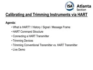
Calibrating and Trimming Instruments via HART. Agenda: What is HART? / History / Signal / Message Frame HART Command Structure Connecting a HART Transmitter Trimming Devices Trimming Conventional Transmitter vs. HART Transmitter Live Demo . What is HART?.

Calibrating and Trimming Instruments via HART
E N D
Presentation Transcript
Calibrating and Trimming Instruments via HART Agenda: What is HART? / History / Signal / Message Frame HART Command Structure Connecting a HART Transmitter Trimming Devices Trimming Conventional Transmitter vs. HART Transmitter Live Demo
What is HART? HART = Highway Addressable Remote Transducer A digital communication protocol designed for industrial process measurement applications. Uses a low-level modulation (FSK) superimposed on the standard 4 to 20 mA current
Revision Year 2.0 1987 3.0 1988 4.0 1989 5.x 1989 – still delivered today 6.0 2001 – never introduced 7.0 2007 – introduction of HART wireless HART History
Three levels of commands • Universal commands • Common practise commands • Device Specific commands HART Command Structure • Universal commands • Model ID • Tag ID • Description • Message • Date • Range Values • Instrument Limits • Process Measurements • Device Status • Common practice commands • Read Variables • Calibration (zero, span) • Initiate Self Tests • Serial Number • Time Constant Values • Device Specific commands • Model Specific Functions • Start, Stop, or Clear Totalizer • Select Primary Variable • Special Calibration Options • PID - SP, Tuning, Etc.
Connecting a HART Transmitter Point-to-point 24V supply Transmitter mA Resistor + HART _ mA Polling address = 0 ! => HART + mA signal HART Communicator
Connecting a HART transmitter Multidrop 24V supply Resistor + _ 4 mA (fixed) ... HART Communicator Addr=1 2 15 Transmitters (max 15 pcs), fixed 4 mA current, Only PV output, different addresses (not 0 !)
Trimming Devices CommunicatorsSmart Calibrators
MC5 Internal Connections MC5 24V supply Transmitter mA Resistor +24V + _ Ground mA HART HART Communicator
HART vs. Conventional Transmitter (1of 2) Conventional transmitter Input 4 … 20 mA • Adjustments: • Zero • Span
HART vs. Conventional Transmitter (2 of 2) HART transmitter Input section Conversion Output section Range Transfer Function PV AO Input 4 .. 20 mA A/D D/A Digital trim Analog trim PV AO
Live Demo Presented by: Ned Espy – Consulting Director Beamex, Inc. Office: 770-951-1927 Mobile: 404-386-8158 ned.espy@beamex.com www.beamex.com