Wave Propagation
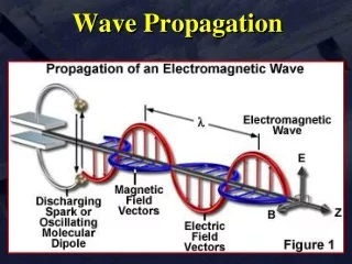
13. Wave Propagation. Electrical to Electromagnetic Conversion. Electrical energy fed into transmitting antenna must be converted to another form of energy for transmission. Transmitting antenna converts its input electrical energy into electromagnetic energy.

Wave Propagation
E N D
Presentation Transcript
13 Wave Propagation
Electrical to Electromagnetic Conversion • Electrical energy fed into transmitting antenna must be converted to another form of energy for transmission. • Transmitting antenna converts its input electrical energy into electromagnetic energy. • Receiving antenna intercepts transmitted wave and converts it back into electrical energy.
Electromagnetic Waves • Electromagnetic field • Electric field and magnetic field. • Radio-frequency interference (RFI) • Undesired radiation from radio transmitter.
Electromagnetic Waves • Electromagnetic interference (EMI) • Noise. • Maxwell’s equations • Gauss’s law for electric fields, Gauss’s law for magnetic fields, Faraday’s law, Ampère-Maxwell law.
Electromagnetic Waves • Wavefronts • Surface joining all points of equal phase. • Isotropic point source • Electromagnetic wave radiates equally in all directions from point source in free space; spherical wavefront results. • Isotropic source • Radiates equally in all directions.
Waves Not in Free Space • Reflection • Radio waves reflected by any medium. • Angle of incidence equal to angle of reflection. • Refraction • When waves pass from a medium of one density to another medium with a different density.
Waves Not in Free Space • Diffraction • Waves traveling in straight paths bend around an obstacle.
Ground- and Space-Wave Propagation • Four modes of getting radio wave from transmitting to receiving antenna: • Ground wave • Space wave • Sky wave • Satellite communications
Ground- and Space-Wave Propagation • Ground-Wave Propagation • Ground wave • Radio wave that travels along Earth’s surface; changes in terrain strong effect. • Attenuation of ground waves directly related to surface impedance of Earth; function of conductivity and frequency. • Only way to communicate into ocean with submarines.
Ground- and Space-Wave Propagation • Space-Wave Propagation • Direct wave most widely used mode of antenna communications; limited to line-of-sight transmission distances. • Propagated wave • Direct from transmitting to receiving antenna; does not travel along ground.
Sky-Wave Propagation • Sky Wave • Ability to strike ionosphere, be refracted from it to ground, strike ground, be reflected back toward ionosphere. • Skipping • Refracting and reflecting action of ionosphere and ground.
Sky-Wave Propagation • Sky Wave • Method of long-distance transmission. • Ionosphere • Three layers designated from lowest level to highest level as D, E, andF.
Sky-Wave Propagation • Effects of the Ionosphere on the Sky Wave • Critical frequency • Highest frequency returned to Earth when transmitted vertically under given ionospheric conditions. • Critical angle • Highest angle wave of specific frequency can be propagated and returned from ionosphere.
Sky-Wave Propagation • Effects of the Ionosphere on the Sky Wave • Maximum usable frequency (MUF) • Highest frequency returned to Earth at given distance.
Sky-Wave Propagation • Effects of the Ionosphere on the Sky Wave • Optimum working frequency • Most consistent communication and best one to use. • Skip zone • No signal will be heard.
Sky-Wave Propagation • Effects of the Ionosphere on the Sky Wave • Fading • Variations in signal strength that occur at receiver during time signal received. • Ionospheric storms • Cause radio communications to become erratic. • Tropospheric scatter • Signal aimed at troposphere.
Satellite Communications • Satellite Communication System • Uplink (transmitter) • Orbiting satellite • Downlink (receiver) • Uplink and downlink • Earth station (ground base).
Satellite Communications • Satellite Communication System • Transponder • Electronic system performing reception, frequency translation, retransmission. • Attitude controls • Orbital corrections on satellite. • Footprint • Limited coverage area.
Satellite Communications • Orbital Patterns • Orbital patterns of satellites elliptical. • Perigee (closest distance of orbit to Earth). • Apogee (farthest distance of orbit from Earth).
Satellite Communications • Orbital Patterns • Geostationary orbits use equatorial orbit. • Look angle • Azimuth and elevation angles for Earth station antenna calculated so correct satellite can be seen.
Satellite Communications • Global Positioning System • Pinpoint geographic location information. • GPS satellites transmit position data signals; GPS receiver processes time to receive each one.
Satellite Communications • Multiplexing Techniques • Frequency-division multiple access (FDMA). • Time-division multiple access (TDMA).
Satellite Communications • Earth Station Distance to and from Satellites • Distance from Earth station to satellite; estimate time delay for transmitted signal to travel from Earth to satellite and back. • See Table 13-2: Earth Satellite Measurements
Satellite Communications • Earth Station Distance to and from Satellites • Code division multiple access (CDMA). • Very small aperture terminal (VSAT) fixed satellite communication systems. • Ultrasmall aperture terminal mobile satellite (MSAT) systems.
Satellite Communications • Satellite Radio • U.S. two satellite radio services • XM and Sirius. • XM Satellite Radio service • Two geostationary satellites. • Sirius Satellite Radio service • Three satellites in inclined orbit.
Figure of Merit and Satellite Link Budget Analysis • Figure of merit (G/T) • Provides performance measure for different satellite Earth stations. • Larger the figure of merit (G/T), the better the Earth station system. • Satellite link budget • Verifies required C/N and signal level to satellite receiver will be met to ensure satellite receiver outputs signal that meets specifications.
Figure of Merit and Satellite Link Budget Analysis • Satellite Link Budget Calculation • Evaluates quality of satellite link signal in terms of C/N; makes sure satellite link meets required C/N specifications. • Determined from both uplink budget and downlink budget. • Free-space path loss • Attenuation of RF signal as it propagates through space and Earth’s atmosphere to and from satellite.