Download

1 / 53
530 likes | 739 Vues
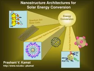
Two Cases of Low Grade Energy and Solar Energy Conversion Systems. Zhaolin GU, PhD, Professor Xi’an Jiaotong University, Xi’an, China 17th October, 2006, In Keio University. CONTENT Brief introduction of Xi’an City Brief introduction of Xi’an Jiaotong University

E N D
Two Cases of Low Grade Energy and Solar Energy Conversion Systems Zhaolin GU, PhD, Professor Xi’an Jiaotong University, Xi’an, China 17th October, 2006, In Keio University
CONTENT • Brief introduction of Xi’an City • Brief introduction of Xi’an Jiaotong University • Case 1-Thermal Energy Recovery of Air Conditioning System • Case 2-Central solar hot water supply system assisted by heat pump
Introduction of Xi’an • Xi’an was the champion among the six ancient Chinese cities, and has the longest history in China. • Xi’an served intermittently as the capital city of 11dynasties in the ancient China. • Some attractions: • Terra-cotta Warriors & Horses Museum (Qin dynasty, 221-206 B.C.); • Yang-ling Archaeological Museum (Han dynasty, 153-126 B.C.); • The Great City Wall built in the Ming dynasty; • The Small and Big Wild Goose Pagodas built in the Tang dynasty; • The Bell and Drum Tower of the Ming dynasty
The Terra-cotta Warriors & Horses Museum Pit No. 1
The Terra-cotta Warriors & Horses Museum Pit No. 2
Introduction of Xi’an Jiaotong University • One of the nine leading universities in China directly administered by the Ministry of Education, with more than 1,600 professors and associate professors • A comprehensive university covering natural science, engineering, medicine, economics, management, liberal arts and law, with engineering as its main focus • An enrollment of over 32,000 full-time students, of whom more than 12,000 graduated students and about 1000 international students
Introduction of School of Human Settlements and Civil Engineering • Four departments: Architecture, Civil Engineering, Building Services, Environmental Science and Technology • Center of City Climate and the Built Environment • Over 70 personnel, with 36 professors and associate professors • Over 700 full-time students and more than 100 graduated students
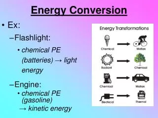
Introduction of Refrigeration and heat pump cycle
Refrigeration and heat pump cycle T 2 3 1 4 S The principle of refrigeration and heat pump cycle and the working fluid—refrigerant
Refrigeration and heat pump cycle • Air conditioning system: • The evaporator absorbs the heat from indoor air via the refrigerant evaporating process. • The condenser discharges the heat of refrigerant to the surroundings via the refrigerant condensing process. • Heat pump system: • The evaporator absorbs the heat from outdoor air via the refrigerant evaporating process. • The condenser discharges the heat of refrigerant to indoor air or heat demand, via the refrigerant condensing process.
Case 1 Thermal Energy Recovery of Air Conditioning System
Case 1-Thermal Energy Recovery of Air Conditioning System — Background 1 • Most hotels and restaurants provide both cooling and heating services for customers in summer. • Hot water supplying system, by electricity or other fuels (oil, gas, coal), and air conditioning system provide heating and cooling load, respectively. • The rejected (sensible and condensation) heat from the compressor discharge gas of air conditioning systems is a readily available energy source.
Case 1-Thermal Energy Recovery of Air Conditioning System — Background 2 • The outlet temperature of cooling water for air conditioning system could reach between 35 to 40℃ . • The heat recovery from air conditioning systems, for water heating might decrease not only the consumption of primary energy, but also the calefaction (warming) of the air surroundings.
Case 1-Thermal Energy Recovery of Air Conditioning System — Background 3 • The staggering and uncontinuity of hot water demands results in an accumulator for the heat recovery system. • Water is widely used for sensible heat storage and hot water is thus produced, directly. • Phase change materials (PCMs) are able to change phase at constant temperature and store large quantities of energy
Case 1-Thermal Energy Recovery of Air Conditioning System — Background 4 A large number of organic and inorganic substances are known to melt with a high heat capacity of fusion in any required temperature range. • Chemical stability, including no chemical decomposition, non-poisonous, non-flammable and non-explosive, Non-corrosiveness, etc. • High latent heat of fusion per unit mass • High specific heat & high thermal conductivity • Small volume changes during phase transition • Exhibiting little or no sub-cooling during freezing
Case 1-Thermal Energy Recovery of Air Conditioning System — Background 5 • Paraffin wax calls growing attention to being a good media for energy storage, which is mainly used in solar energy storage as a kind of PCMs. • Paraffin wax is not compliant for heat reclamation of air condition systems. • Some solvents are investigated for paraffin wax to adjust the phase change temperature.
Characteristics of PCMs — Melting of Paraffin wax Melting temperature curve of paraffin wax
Characteristics of PCMs — Freezing of Pure Paraffin wax Freezing temperature curve of paraffin wax
Characteristics of PCMs — Paraffin wax with liquid paraffin Freezing temperature curve of the mixture containing 30% liquid paraffin Melting temperature curve of the mixture containing 30% liquid paraffin
Characteristics of PCMs — Paraffin wax with liquid paraffin Table 1. Freezing temperature and fusion heat capacity of the sample (paraffin wax + liquid paraffin)
Characteristics of PCMs — Paraffin wax with lauric acid Temperature change of mixture containing 11% lauric acid during freezing Temperature change of mixture containing 11% lauric acid during melting
Characteristics of PCMs — Paraffin wax with lauric acid Table 2. Freezing temperature and fusion heat capacity of the sample (paraffin wax+ lauric acid)
Characteristics of PCMs — Volume expansion/contraction in phase change process The results indicate that the volume change of paraffin wax from liquid to solid phase is accompanied by a volume contraction. The volume contraction is less than 12%.
Heat recovery system — Test Schematics of the air conditioning system with thermal energy reclamation devices
Heat recovery system — Test Refrigerant temperature curves of the thermal accumulator, condenser and evaporators during thermal energy storage
Simulation of the PCM melting process of the heat storage device—1 Hot fluid Inlet The concentrically mounted pipe heat storage device and the isothermal curves of PCM at t = 200s.
Simulation of the PCM melting process of the heat storage device—2 The isothermal curves of PCM at t = 800s (Left) and t = 1,100s (Right).
Simulation of the PCM melting process of the heat storage device—3 The sectional temperature distribution at t = 1,100 s.
Summary of heat recovery from air conditioning system • Latent heat thermal energy storage systems can be used to recover the rejected heat from air conditioning systems. • The volume expansion / contraction ration of the phase change process is below 12%. • The test results show that the hot water temperature produced by the recovery system reaches the expected about 35C and meets the temperature demand of domestic water for washing and bathing. • Assisted electric heater should be designed on the hot water pipe.
Case 2 Central solar hot water supply system assisted by heat pump
Case 2 – Central solar hot water supply system assisted by heat pump: Background 1 • Thermal utilization of solar energy is a developed technology and popular in China, especially for hot water supply. • The central solar hot water supply system (CSWS) producing 2~20 tons hot water per day is being adopted by more and more buildings to satisfy massive users simultaneously in China. • Solar radiation is not stable and subject to change greatly in different weather, season of a year and regions.
Case 2 – Central solar hot water supply system assisted by heat pump: Background 2 • When there is no sufficient solar radiation in the daytime due to several cloudy or rainy days, or weak radiation in the winter and early spring, the desired temperature of hot water could not be reached. • A group of large auxiliary electrical heating appliances should always be placed into the water tank of the CSWS system to deal with atrocious weathers. • Generally, the total power of the electrical heaters in a 2 ton tank reaches 18~36kW to ensure that the system can be operated under any situation.
Case 2 – Central solar hot water supply system assisted by heat pump: Background 3 Flow chart of Heat pump assisted Central Solar hot Water supply System (HCSWS).
Case 2 – Central solar hot water supply system assisted by heat pump: Background 4 • The heat pump could absorb the heat from the low-temperature thermal resource and discharge it to the high-temperature one effectively. • The Heat pump assisted Central Solar hot Water supply System (HCSWS) has the both advantages of the heat pump and CSWS.
Case 2 – The HCSWS system Test Experimental facilities of HCSWS in laboratory
Case 2 – The HCSWS system Test – Meteorological data Daily solar radiation and average atmospheric temperature in Xi’an city, 2005.
Case 2 – The HCSWS system Test – Some fitted formula The inlet temperature of water, entering into the HCSWS system. In winter, the inlet temperature of water is set as 5 ℃.
Case 2 – The HCSWS system Test – Some fitted formula The evaporating temperature of the heat pump is directly affected by the atmospheric temperature.
Case 2 – The HCSWS system calculation – Assumptions • The absorbed heat only relies on the coefficient of the evacuated tube solar collectors. • The condensing temperature is only related to the initial and final temperature of the water tank. Moreover, the input power of the recycle water pump and fan keeps constant. • This system could just supply 2 tons, 55C water to users at 18 o’clock everyday and the hot water could be used up before the next day. • Compared to the directly electric heater, the power of the auxiliary heater is 36kW and its efficiency is 95%.
Case 2 – The HCSWS system calculation – Mathematical model The heat absorbed by the solar unit: The condensing power of heat pump: The evaporating power based on MT80 technical handbook, Danfoss- Maneurop company: The input power of heat pump:
Case 2 – The HCSWS system calculation – Daily performance The daily performance coefficient of the heat pump: The daily performance coefficient of HCSWS system: The daily performance coefficient of the direct electric heating CSWS system:
Case 2 – The HCSWS system calculation – Annual performance The annual performance coefficient of heat pump: The annual performance coefficient of HCSWS system: The annual performance coefficient of ECSWSsystem: