Download
1 / 39
520 likes | 852 Vues
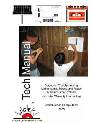
Tech Manual. Diagnosis, Troubleshooting, Maintenance, Survey, and Repair of Solar Home Systems (Includes Warranty Information) Border Green Energy Team 2005. v2. TECH MANUAL THAI Solar Home Systems Diagnosis Troubleshooting Maintenance Survey Repair Warranty Claims.

E N D
Tech Manual Diagnosis, Troubleshooting, Maintenance, Survey, and Repair of Solar Home Systems (Includes Warranty Information) Border Green Energy Team 2005 v2
TECH MANUAL THAI Solar Home Systems Diagnosis Troubleshooting Maintenance Survey Repair Warranty Claims Border Green Energy Team TOPS 34/53 Mae Sod – Mae Tao Rd Mae Sod, TAK 63110 055-542-068 Written By Andrew Pascale Chris Greacen Designed By Andrew Pascale Edited By Salinee Tavaranan Walt Ratterman Border Green Energy Team c/o TOPS PO Box 66 Mae Sod, TAK 63110 Version 2 November 2005
In this Manual PAGE 1 2 3 4 5-6 7 8-12 13 14 15 16-17 18 19-20 20-21 22 23-24 25 26-27 28 29-30 31 32-34 35 36 How to Use this Manual Example System Survey Form SHS Serial Number Locations Warranty Claim Form Safety Useful Tools to Have in Your Bag Using the Multimeter Visual System Diagram Basic Electrical System Diagram Inspection a Solar Home System Solar Panel Sighting Overall System Connections Understanding the Inverter Solar Panel Survey and Diagnosis Junction Box Check (if needed) Battery State of Charge Charge Controller Check Battery Maintenance Inverter Inspection AC Wiring Inspection Blank NOTES Forth Inverter Manual Solartron Solar Module SP-120 3K EBB 125 Battery Specifications
How to Use this Manual This manual is intended as a reference and constant companion while you survey, inspect, maintain, and repair Thai Solar Home Systems. This manual explains SHS operation, basic maintenance, and basic system repair. For further reading on electricity, solar home system design, proper solar home system use, and the general operation of individual SHS components a second more in depth manual has been provided. This manual will help you determine the health of a Thai Solar Home System. As a SHS technician, you are not only interested in fixing or filing claims on broken systems, but in preventing future system breakdowns and providing for system sustainability. Preventing future SHS failures will insure longer system use and SHS user satisfaction, reduce the amount of warranty claim procedures needed, and reduce future maintenance and repair by the responsible party (right now is Aw-baw-daw). The primary ingredient in preventing future system breakdown is education of the SHS user. A technician should pass on as much system knowledge as possible and demonstrate all maintenance procedures to the SHS user. This manual describes many individual processes for Thai Solar Home System diagnosis. An effort has been made to place them in an order that will help the technician get a feel for what is happening with the system as a whole rather than with just one component. Focusing on the most obvious failure point without taking into account the rest of variables surrounding the SHS may lead to an incorrect system diagnosis. As well finishing a survey without looking at possible future problems may lead to a SHS failure shortly after you determine the system is working well. For example a system that is currently working but has a banana tree growing in front of the panel will not be working well for much longer. Educating the user on panel shading and cleanliness can save you a return trip to the house and the user the inconvenience of a “broken” system. This manual can help you with most of what is expected from a SHS technician: system diagnosis, user education, basic system maintenance and repair, and warranty claim procedures. What is not covered? Internal Inverter Repair. Internal repair of the inverter is not covered nor should it ever be attempted. This will both void the warranty if it applies and is potentially very dangerous. A professional and respectful attitude. Such an attitude will facilitate your interaction with the homeowner and local energy authorities, but it will help you diagnose systems equally and thoroughly every time as well as increase your effectiveness. Planning for the future. Thai SHS will only prove ultimately useful if all parties involved (installer, local government, technician, user) can insure long term SHS operation and provide for fair and effective maintenance and equipment replacement. You are a key link in this process. You will be the voice of the villager, the local technical and logistical expert, as well as the direct link with the Aw-baw-daw. 1
SHS Serial Number Locations The Battery Serial Number is the leftmost 7 digit number. 4708956 The FORTH Serial Number is located on the bottom of the unit behind the connection strip. The Solar Panel Serial Number is located on the sticker on the back of the panel. 3
SAFETY Any energized electrical system is by nature dangerous. In almost all cases improper connection of an electrical system can result in damage to the system, yourself, others, and tools. Proper precautions should always be taken and a few simple safety rules followed. Safety procedures and rules will be reinforced with every system you safely survey, diagnose, and repair especially as you demonstrate and verbally pass along safe system maintenance and practices to the homeowner. Time is on your side. Many accidents happen because people are rushing or become impatient. Patience and thoughtful action not only make for a safer working environment but also show professionalism. Look at every system as a whole. Always think about how your present action will affect your safety, others safety, and the safety of the system. Don’t get so caught up focusing on a single system component that you allow another part of the system to be compromised (eg. creating a battery short circuit while disconnecting and troubleshooting the solar panel). The battery comprises the single biggest danger in a Solar Home System. Treat the battery and all battery connections and wires with extra care. The biggest danger when dealing with a battery is a short circuit across the terminals! A short (circuit) is a direct physical conductive connection between the positive and negative terminals of the battery. This is a condition of extreme and possibly lethal danger! Batteries can release a huge amount of electricity when shorted. Batteries have also been known to explode, spraying harmful acid those nearby. A short can be created by placing anything metal across the terminals (metal tools can and will create a short circuit – when surveying a system never place a tool on the battery), by connecting a wire across the terminals, or by accidentally crossing the wires attached to each terminal. A short can happen anywhere battery voltage is present is system wiring!! 5
Safety Continued Care should be taken when working around the inverter. At the connection strip many voltages and possible currents are in close proximity. When disconnecting or connecting wires from the inverter make sure to keep wires separated. When taking measurements on the inverter, take a moment and double check that multimeter setting you are using is correct for the points you intend to measure across. Batteries pose a further danger due to internal acid, outgassing of combustible gas, and the inclusion of environmentally unfriendly materials in battery manufacture. Battery cell electrolyte is an acid. As you will be inspecting every cell on every battery you come across take precautions to protect your eyes and always have water close at hand if acid somehow reaches your eyes. Make sure to wash your hands after dealing with battery acid. Battery acid is especially harmful to clothes avoid spilling acid on your clothes. Washing your hands immediately is easy but washing your clothes immediately and thoroughly is not so easy. Combustible battery gas can build up if batteries are not properly ventilated. Do not store batteries in a box or smoke next to an outgassing battery. With all of the harmful materials in batteries, battery disposal should also be attended to carefully. Dead or defective batteries should be recycled, returned to the manufacturer, or disposed of safely. If not already in place we hope to set up a battery recycling/disposal system as part of our project. All SHS AC wiring and circuits pose a threat and can deliver a lethal electrical pulse. Shorts should be avoided at all costs, both in light system wiring and at the outlet. Normal caution should be taken around light bulbs. Broken glass is not fun to deal with. 6
Useful Tools And Items To Have In Your Tool Kit . Multimeter and Probes . Pen and Notebook . System Diagrams (Page 13, 14) . Medium Spade Head Screwdriver . Medium Phillips Head Screwdriver . Small Spade Screwdriver . Flashlight . Wirestrippers + Cutters . Electrical Tape (Red and Black) . Pliers . Warranty Claim Forms (Page 4) . SHS Survey Form (Page 2) . Hydrometer . Distilled Water . Wire Brush . Cleaning Rag . Light Bulbs . Ballasts . Wire Spade Inverter Crimp . Wire Circle Battery Crimp 7
Using the Multimeter OFF V~ 600 600 V― 200 200 2m 20 A― 20m 2 200m 200m 2M 10A 200k hFE 20k °C Ω Ο))) 2k 200 ! Max 600V 200mA MAX 10A Max 10 ADC COM VΩmA 8
19.3 The Multimeter The multimeter is your window to the flow of electricity and the potential present at a point of your choosing in a Thai Solar Home System. It is a tool for observing the electrical properties of a circuit, wire, or connection. The multimeter will be your main tool for diagnosing both the status of any component in the system as well as the overall health of the system. The multimeter consists of a compact diagnostic unit and two pluggable probes that will be used to interact with Solar Home System wiring. The central unit houses the diagnostic circuitry, an LCD display, three plug ports, and a central moveable switch that allows a technician to select measurement type as well as measurement range. There are many different brands of multimeter usually offering the same basic set of measurement types and ranges as well as various “extras”. Basic measurement types include DC voltage (V—), AC Voltage (V~), DC Current (A—), and Resistance (Ω). Each of the basic measurement types has a range selection. The range setting allows a user to adjust the sensitivity of the meter to the item being measured. Always overestimate on your range selection. For example, if you want to measure a 12v battery, select the 20V, 200V, or 600V DC setting. Looking at the dial: DC voltage (V—) measurements are allowed at 600v, 200v, 20v, 2v, and 200mV ranges. AC Voltage (V~) measurements are allowed at 600v and 200v. DC Current (A—) measurements are allowed at 2mA, 20mA, 200mA, and 10A. Resistance (Ω) measurements are allowed at 2MΩ, 200kΩ,20kΩ,2kΩ, and 200Ω. continuity Ο)))) temperature (°C) Transistor test (hFE) 9
200V DC Voc, Vbat, Vcc 600V AC Inverter AC Out OFF The Multimeter: making measurements The diagrams below show correct dial settings and probe receptacles for common measurements. The multimeter has two wires. The black wire should always be plugged into the “COM” recepacle. To measure voltage or continuity, the red wire should be plugged into the “VΩmA” receptacle. For purposes of safety we are going to tape over the “10 ADC” receptacle. None of the measurements made while diagnosing a Solar Home System will require the “10 ADC” port. Taking the wrong measurement with a probe plugged into this receptacle is dangerous to both the technician and the equipment. 10
The Multimeter: making measurements • When taking a measurement with the multimeter you always need to think the full process out first. • Taking a measurement requires that you: • 1) Know what you want to measure • 2) Have an idea of the range you are going to measure in. • 3) Identify the wires, terminals, or terminations you are going to measure across. • 4) Make sure that you will be able to take a safe measurement. • 5) Select the correct measurement type and range on the meter. Overestimate the range if you are unsure. You can always dial down after confirming the range to get a more precise reading. • 6) Plug the probes into the correct ports on the meter for the measurement. • 7) Double check: are you sure the probes are in the right receptacle? • Only then can you: • 8) Touch the probes to the appropriate points to take the measurement. • The table below shows settings for most of the measurements you will need to perform 11
The Multimeter: measuring continuity Continuity measurement allows you to tell if a wire is broken or a connection has come loose without having to inspect the whole wire or expose the conductor. It can also tell you if any two points are electrically connected. Continuity Settings: If a wire has continuity it means that the wire has no breaks and is a continuous whole. The multimeter measures continuity by sending a very small amount of electricity is on one probe. If you provide a continuous path for the electricity to flow to the other probe, you will hear a beeping sound. You will find through testing of the objects around you that only readily conductive materials (like metal) can provide such a path. 000 12
Inspecting A Solar Home System Overall Approach: 0) Solar Panel Location, Shading, Cleanliness 1) Make Sure Sun is shining on Panel. 2) Overall System Connections and Layout 3) Inverter Operation and Inspection 4) Solar Panel Multimeter Inspection (Voc) 5) Junction Box Inspection (if needed) 6) Battery State of Charge (Vbat) 7) Charge Controller Inspection (Vcc) 8) Battery Maintenance 9) Inverter and AC Wiring Inspection (Vac) The key to the sustainability of SHS systems is educating users! Aside from the immediate goal of replacing and fixing broken parts, this is a technicians primary responsibility. 15
Solar Panel Siting X Solar panels need sunlight to make electricity. To ensure the module makes as much electricity as possible we must avoid shading as much as possible in all hours of the day and all seasons of the year. 16
Solar Panel Siting, Orientation, Upkeep • You can’t make clouds go away or make the rain stop but you can make sure the panel is clean, oriented correctly, and free from shading. • Orientation of the solar panel in Thai solar home systems is usually correct (the panel should face due south and be tilted at 16 degrees from horizontal). But shading can be a big problem. Shading sources or any covering (dirt, leaves, …) should be removed if possible. And the technician should explain to the system owner that reducing shading is essential. If a shading source cannot be easily remedied (a house, a big tree, an antenna) you should make sure to inform the system user and possibly suggest a way to remedy the problem such as moving the panel or antenna. • Solar Panel Checklist: • Orientation (South and tilt of 16 degrees for Tak Province). • Long term shading • Shading you can remedy or possible future shading • Panel is dirty or has other covering • Make sure to explain all applicable solar panel issues with the homeowner. Future shading (a tree growing in front of panel) and panel cleanliness should be discussed with all system users. • How can shading and dirt affect the system and your system diagnosis? • Short term effects. • 1) In sunny weather you will see a much lower power output than expected or observed on other houses close by. • 2) The homeowner gets very few hours of use out of system even after a long sunny day (note: this could also be explained by a bad battery). • Long term effects. • 1) Battery loses capacity as it never fully charges. Battery becomes sulfated. 17
Check Overall System Connections and Layout screw screw 1) Remove terminal strip cover from inverter. It is held on by two screws on the bottom of the inverter. Keep screws in a safe place. Do not lose them. 2) Check all inverter connections. Make sure terminations are clean and tight. 3) Make sure all inverter terminations are in good health and marked correctly for polarity (red for + , black for -). 4) Make sure battery terminals are clean, terminations tight, and wires marked correctly for polarity (red for +, black for -). 5) Make sure battery is in a good location. If the battery is in a high traffic area, make sure it is protected from abuse and playful hands. 6) If the roof is potentially leaky, recommend a makeshift roof over the top of the inverter panel to deflect water or debris. 7) Clear dirt and debris from inverter venting. 8) Advise System user on all of the above. The better you educate the homeowner, the less work you may have to do in the future and the more potentially sustainable the Solar Home System. Note: a heavy cloth cover on the inverter may cause overheating problems. The inverter needs to “breathe”. 18
What the LEDs mean as far as we can tell. These lights are somewhat useful in diagnosing a system, but often they are more confusing than helpful. System Indicators (Top) RED LED – This LED indicates Solar Panel status. If the light is blinking, the inverter is not receiving usable power from the Solar Panel. This can either indicate the sun isn’t out, the sun is too weak to produce usable power, or there is a problem with the Solar Panel, wiring from the Inverter out to the panel, or with connections at the inverter. (Mid) YELLOW LED – Battery indicator. As far as we can tell this light means very little. It can be on even if the battery is disconnected. It basically means that some voltage source is present on its DC connectors. (Bottom) GREEN LED – A solid light usually indicates a load is drawing power from the inverter (light bulb, tv) although this is not always true. A blinking green light indicates a short or overload in the AC wiring. See AC wiring section for the proper AC wiring diagnosis procedure. Battery Indicators Take these LEDs with a grain of salt. Your multimeter is much more trustworthy. The following is taken from the Solartron Manual and are what the lights are supposed to indicate. Is something missing here? (Top) GREEN LED – Battery voltage is 13.9v or higher (Mid) YELLOW LED – Battery voltage is 12.5v and 13.8v (Bottom) RED LED – Battery voltage is below 11.3v Understanding the Inverter LEDs 19
About The Inverter Terminal Strip The Inverter terminal strip is almost as straightforward as it seems. On the left side of the strip, marked by the picture of the battery, are the positive and negative screw connections for the battery. Connected to these two screw terminals should be two spade terminated color coded (red for +, black for -) wires from the battery. The red + connection at the inverter should be connected to the + terminal of the battery. Next to that on the left are the positive and negative screw connections for the Solar Panel. Connected to these two screw terminals should be two spade terminated color coded (red for +, black for -) wires from the solar panel. Next to the – solar panel terminal screw should be three unused screw terminals: the L, N, and Ground. These are inverter outputs. You will most likely never see any of these used. The Solartron user manual suggests that the L and N could be connected to an AC power delivery circuit. Ground is not used in most AC circuits in Thailand. The large plug to the right of the connection strip is the inverter output to the AC lights and power circuits Solar Panel Survey and Diagnosis Surveying Solar Panel operation involves measuring the Open Circuit Voltage (Voc) of the panel. Based on Voc you should be able to judge the health of the Solar Panel. On the following pages you will find multimeter and circuit configurations for measuring Voc. You only need to inspect the Solar Panel Junction Box if the sun is shining on the panel and you get a Voc measurement below 17V. 20
How to measure panel open circuit voltage (Voc) Do Not allow loose wire termination to touch any other terminals!! Black Black Red Black Red Red Double Check Plug Configuration! RECONNECT SOLAR PANEL WIRES TO INVERTER AFTER MEASUREMENT!! 19.3 21
Junction Box Check (only if panel Voc is less than 18 volts in good sun) Disconnect the Positive Solar Panel wire from the Inverter before starting Junction Box Inspection. Visual Inspection 1) Melted Terminal Strip 2) Diode Reversal 3) Darkened Wires A B C 00.0 Repair 1) In the case of a melted terminal strip, replace terminal strip. 2) In the case of diode reversal, remove diodes and store in J-box. 3) If there are darkened or burnt wires, trim and re-terminate wires if possible. If not, tape burnt part of wires well. Multimeter Inspection of Junction Box Voltages Between A and B = ~9-10v Between B and C = ~9-10v Between A and C = ~17-21v 22
Battery State of Charge We measure battery state of charge (how “full” of energy the battery is) by measuring the voltage. Higher voltage, in general, means higher state of charge. If the state of charge is high, we can be pretty sure that the battery is healthy. If it is low, then the battery might be sick, or it might just be very discharged and in need of charging. The longer a battery is left in a discharged state, and the deeper it is discharged, the more the battery’s “health” declines. While we use battery voltage to “measure” battery state of charge, there are complicating factors: battery voltage also depends on other factors such as whether the battery is being charged or being discharged at that moment, how old the battery is, and what the temperature is. When batteries are charging, their voltage is higher than when they are not charging. Similarly, when they are being discharged, their voltage is lower than when they are at rest. Older batteries have lower resting voltages. Low temperatures mean lower voltage. When diagnosing a battery, your first source of information should be the system user. The user will be able describe long term battery use characteristics. How many hours do they get a night from the battery? Has the system always worked this way? Is there a pattern (bad performance coincides with the rainy season)? Are there signs of system over-use (too many appliances or high wattage appliances)? You should then put this together with what you have observed about the sighting and shading of this system’s solar panel? Can weak battery performance explained by factors surrounding the solar panel? If so, you should make whatever solar panel changes are necessary and possible and explain the problem to the homeowner. On top of that you should fully inspect the battery. Does one of the cells use a lot more water than the others? Are there any signs of obvious cracks? Battery maintenance is not covered on the flow chart but it is detailed on the pages following the flow chart. As a tech you will be checking the water level on all battery cells, refilling cells as needed, and educating the homeowner on battery maintenance. You will also be making sure battery contacts are clean and tight and conditions surrounding the battery are safe. Maintenance needs to be done regularly in order to be effective. Often the best cure for an ailing battery is to ensure that it gets fully charged. Ask the system user to try to just use one light at night for the next few days to let the battery charge up fully. 23
How to measure Battery Voltage Vbat Then Measure Battery Voltage (Vbat) as shown. Voltmeter should be on 200v setting. Battery measurement should be between 3v – 14.5v Black Red Disconnect the + battery connection between the Charge Controller and the Battery. Red Black DO NOT RECONNECT (+) BATTERY WIRE AS IT WILL BE USED FOR THE NEXT MEASURMENT! 11.9 Black Red 24
Charge Controller Check • The charge controller keeps the battery from being overcharged. If it fails, it generally fails in a way that keeps your battery from being charged at all. Talking with the system user will give a good indication of whether the charge controller is working or not. • Indications the Charge Controller portion of the FORTH unit may not be working: • The charge controller makes a loud beeping sound. • The system worked for the first month, but the lights do not turn on anymore and the battery voltage is low. • The homeowner has had to direct connect the solar panel to the battery in order to get the system to work. • The battery plates are not covered with electrolyte, or the owner has to add water frequently (the battery is over-charging). • The battery’s plates are covered with white substance (sulfate). • To further check if the Charge Controller is functioning properly, you are now going to measure the Charge Controller output voltage (Vcc). • This should only be done during a time when sunlight is hitting the panel. Multimeter should be set to 200V DC. Make sure the + connection is removed from the battery.A good Vcc measurement will be greater than 13.5 V. Red Red Black 14.2 Black After the Vcc measurement you should reconnect + wire to positive battery terminal. 25
Battery Maintenance • Battery Maintenance is important for continued system health. Proper battery use (not connecting it to direct DC systems without regulation), maintenance, and regular complete recharging can combine to insure that a battery lives a long useful life. As a technician, you will only be spending a short amount of time with the system. You will be able to perform routine maintenance, but more importantly you will be able to pass the importance of battery maintenance on to the system user. Simply telling the owner is not enough; you should demonstrate proper battery maintenance in every house. • Battery maintenance involves cleaning and inspecting the battery, keeping the terminals clean and the battery connections tight, and checking and refilling the DI water in every cell. Proper safety should be followed throughout battery maintenance. Be careful around battery acid and wash your hands after working with the cells. • People may ask why their battery has air bubbles sometimes. Tell them that this means their battery is being charged fully and that this is a good sign. But when batteries bubble they also consume more distilled water. • Battery Maintenance Check List: • Clean and inspect the battery for damage. This means cleaning dirt and dust from the battery. While you are doing this you can inspect the battery for damage and cracks. 26
Battery Maintenance 2) Clean the terminals and insure tight and solid connections. Terminals will gather dirt and corrosion over time. Terminals can either be scrubbed lightly with a wire brush or cleaned with baking soda and a rag. Ensure a solid tight metal to metal connection between the battery terminal and wire termination. 3) Check the water level in every cell. Look for an especially “thirsty” cell as this can mean a cracked container or weak cell. A battery with an exceptionally “thirsty” cell should be considered bad and replaced. Refill water in every cell to the bottom lip of the red cell opening. This should leave enough room for fluid expansion during hot weather as well as fluid boiling when charging at high voltages. This should only be done with distilled water! Acid should only be used on a new dry battery. Extra care should be taken to avoid contaminating the electrolyte (i.e. no, dirt, dust, or debris). A technician should always carry a supply of distilled water while surveying systems as most batteries will need some refilling. 27
Inverter and AC Wiring Inspection If lights or appliances do not turn on there may be a problem with the wiring or the inverter. To check the inverter voltage, measure as shown below: 205 Black Red Ac Voltage can also be measured here. 28
~ HaCo HaCo 10A ON AC Wiring Diagnosis Black Red AC Wiring Diagnosis Measuring the AC Voltage in the outlet usually takes a bit of probe maneuvering. Solid contact is a must! Voltage that jumps around usually means you need to adjust the probe position until you have a solid contact. 205 29
AC Wiring Diagnosis Red Black 205 30
NOTES 31