Head Unit
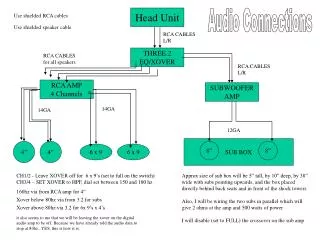
Head Unit. Audio Connections. Use shielded RCA cables. Use shielded speaker cable. RCA CABLES L/R. THREE.2 EQ/XOVER. RCA CABLES for all speakers. RCA CABLES L/R. RCA AMP 4 Channels. SUBWOOFER AMP. 14GA. 14GA. 12GA. SUB BOX. 4”. 4”. 8”. 8”. 6 x 9. 6 x 9.

Head Unit
E N D
Presentation Transcript
Head Unit Audio Connections Use shielded RCA cables Use shielded speaker cable RCA CABLES L/R THREE.2EQ/XOVER RCA CABLES for all speakers RCA CABLES L/R RCA AMP4 Channels SUBWOOFERAMP 14GA 14GA 12GA SUB BOX 4” 4” 8” 8” 6 x 9 6 x 9 CH1/2 - Leave XOVER off for 6 x 9’s (set to full on the switch)CH3/4 – SET XOVER to HPF, dial set between 150 and 180 hz Approx size of sub box will be 5” tall, by 10” deep, by 38” wide with subs pointing upwards, and the box placed directly behind back seats and in front of the shock towersAlso, I will be wiring the two subs in parallel which will give 2 ohms at the amp and 500 watts of powerI will disable (set to FULL) the crossover on the sub amp 160hz via from RCA amp for 4” Xover below 80hz via from 3.2 for subs Xover above 80hz via 3.2 for 6x 9’s x 4’s it also seems to me that we will be leaving the xover on the digital audio amp to be off. Because we have already told the audio data to stop at 80hz...YES, this is how it is.
Will need ring terminals and/or spade terminals for making some of the connections, and the grounds on the amps will be wired directly into the screw-down connectors on the amps Grounding 4 GA 4 GA RCA AMP SUBWOOFERAMP chassis ground lug nut 4 GA Relay 8 GA Ground Dist Block 16 GA 16 GA THREE.2EQ/XOVER Head Unit I believe both the THREE.2 and the Head unit already have pre-wired 16 GA grounding and power wires on them that I cannot change since they are directly connected to the units themselves
Relays Head Unit Blue wire Remote turn on (no fuse needed) Relay To the ground dist block 8GA 15A fuse From the ‘low’ power dist block 8GA 5A fuse 5A fuse 5A fuse 5A fuse Relay output power/signal 16GA 16GA 16GA 16GA antenna THREE.2 Amp 1 Amp 2 I would like to use a connector like this one shown here for the relay, but I don’t know if it will have four outputs on it or not. To feed all four of the devices that need a remote turn on signal. If not I need to make my own. Or just splice in a few power remote turn on wires to the outputs of this connector
Power/Fusing Optima Redtop Battery 2 GA 80A ANL fuse 2 GA 50A inline fuse / 4GA wire SUB AMP 50A fuse High Power Dist Block RCA AMP 40A fuse 8 GA 40A inline fuse / 4GA wire 10A fuse Relay 8 GA 15A inline fuse / 8GA wire 15A fuse Low Power Dist Block THREE.2 5A fuse 5A inline fuse / 16GA wire 10A fuse Head Unit 10A fuse 10A inline fuse / 16GA wire, (always on power) Red wire 10A fuse / 16 GA wireto ignition
This is what the speaker cable will be from liberty cable This is what the shielded rca cable I will be using from parts-express.com