Download
1 / 14
220 likes | 647 Vues
IEEE Joint Communications Chapter - Vancouver. January 12, 2009. Antenna Efficiency Measurements. Andrey Gleener Andrey Gleener R&D Services Ltd. a8421@intergate.ca. P rad. P in - Power applied to Antenna Terminals. P diss. P refl - Power reflected from Antenna Terminals. P in.

E N D
IEEE Joint Communications Chapter - Vancouver January 12, 2009 Antenna Efficiency Measurements Andrey Gleener Andrey Gleener R&D Services Ltd. a8421@intergate.ca
Prad Pin - Power applied to Antenna Terminals Pdiss Prefl - Power reflected from Antenna Terminals Pin Pacc - Power accepted by Antenna Pdiss - Power dissipated in Antenna structure Prefl Pacc Prad - Power radiated Prad tot - Total Efficiency rad = Pacc rad - Radiated Efficiency Prad tot = Pin =(1- |S11|2)rad Antenna Efficiency
Methods of Efficiency Measurements • Antenna Pattern Integration method • Radiometric method • Wheeler Cap method
2 4R2 {pp(,) + px(,)}sin d d Prad= 2Gr 0 0 Prad Prad tot = tot = Pin Pin Antenna Pattern Integration Method Antenna Pattern Integration Method is calculation of Antenna efficiency according to it’s defining formula where Prad is derived by integrating 3D Antenna Pattern measured in anechoic chamber.
ref Pw ( Pw ) - 1 ref Pc Pc rad = ref Pw ( Pw ) - 1 ref Pc Pc Radiometric Method Radiometric method – measurements of the Noise Power generated by Antenna itself. Noise measured from sources with two different temperatures one of which (Tc) is very low and another (Tw) is close to ambient. Tc Tw Radiometric method is practical only for high-directivity antennas
Wheeler Cap Method Wheeler Cap Method is calculation of Antenna efficiency based on measurement of it’s impedance in two conditions: Antenna in open space and Antenna enclosed in Cavity with reflective walls. Wheeler Cap Method does not require anechoic chamber, clear sky or reference Antenna. It does require a Cap though.
Accuracy of Efficiency Measurements David M. Pozar and Barry Kaufman, "Comparison of Three Methods for the Measurement of Printed Antenna Efficiency" IEEE TRANSACTIONS ON ANTENNAS AND PROPAGATION, VOL. 36, NO. 1, JANUARY 1988
H. A. Wheeler, "The radiansphere around a small antenna," Proc. IRE, S. 1325-1331, Aug. 1959. Wheeler Cup Method Harold Wheeler
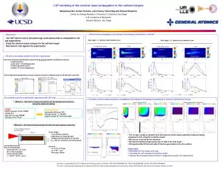
Ronald Johnston and John McRory [S] Z0 2 tot = (Smax)-1+(Smin)-1 "An Improved Small Antenna Radiation-Efficiency Measurement Method " IEEE Antennas and Propagation Magazine, Vol. 40, No. 5, October 1998 waveguide Antenna under test sliding short feed port Antenna is two-port network and in free space is terminated with matched load. Inside the waveguide the terminating impedance is short circuit. Smax tot = |S21|2 S11fs S21= f(S11fs ; S11wg) Smin S11wg
O. Litschke, M. Geissler, D. Heberling, P. Waldow, I. Wolff [S] Zcap ; lcap 1 0.8 Smax 0.6 S11fs 0.4 0.2 0 -1 -0.5 0 0.5 1 Smin S11cap -0.2 2 tot = -0.4 (Smax)-1+(Smin)-1 -0.6 -0.8 -1 (IMST GmbH) "Adoption of the Wheeler-Cap method for measuring the efficiency of mobile handset antennas” c 2003 Antenna is two-port network and inside the cap it is terminated with impedance of the cap (which is short). Generalized transmission line exists between the short and the Antenna.
Plots of S11 extracted from Network Analyzer On both Plots: Blue line - antenna in Free Space Pink line - antenna inside Wheeler Cap Patch Antenna with Air Substrate Patch Antenna with Plastic Substrate