Automated Miniature Solder Press Design for LED Technology Integration
Designing an automated mini solder press for LED technology integration, enhancing efficiency over manual assembly methods. Includes process description, jig assembly, LED sizing solutions, and system overview.

Automated Miniature Solder Press Design for LED Technology Integration
E N D
Presentation Transcript
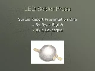
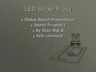
LED Solder Press • Status Report Presentation • Senior Projects I • By Ryan Bigl & • Kyle Levesque
Background Info • This project is for a small business called LEDdynamics, located in Randolph, Vermont. • “LEDdynamics is a custom engineering company specializing in the design and integration of LED technology for end-user and OEM applications.”
Problem statement Design an automated miniature solder press that will… • Be able to solder pre-glued surface mount LED emitters to a metallic circuit board. • Be able to test the LED after completion • Must be faster and more efficient than hand assembly. • System will not need human aid, after initial setup is completed.
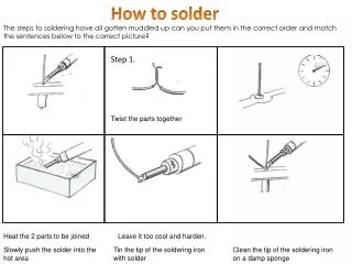
Process Description • Drill Metallic Mounting Circuit Board • Prep soldering area with flux • Glue in surface mount LED’s • Solder the LED leads • Test for failed product
Light Strip Base Sizes • Soldering 2 different strip sizes • Soldering 3 different strip styles
Jig Assembly • 2 pull pins • 2 springs • Adjustable slide support • 2 rail / receivers • Base plate • Front support plate
Solutions • Build a X table with a set jig for metallic circuit boards. • Make a single press/ dual soldering iron system with wire fed solder. • Test the LEDs inline with solder station. • Allow user to initially select predetermined board size and stores data throughout the run.
Full System Overview • 1. Controller • 2. Manifold • 3. Power Source • 4. Wire Feed • 5. Push Cylinder • 6. Solder Cylinder • 7. Solder reels • 8. Soldering Tips • 9. Guidance Track • 10. Solder-Testing Frame • 11. User Interface Board • 12. Data Bus • 13. Test Cylinder • 14. Soldering Power Supply • 15. Test Lead
Part Sizes & Tolerances • LED Dimensions Pad Dimension • Both diagrams are drawn with millimeter dimensions • (both diagrams come from Luxeon Emitter, http://www.lumileds.com/pdfs/AB10.PDF
Pneumatic System Overview • This pneumatic system involves; • Double-acting telescopic cylinder • Double-acting cylinder with double-ended adjustable cushioning • Manifold for air flow control • Start push button
Electrical Concepts Twin motor controllers AC to DC power supply LCD Solder Heat units Test unit EStop Triple solenoid block Selector switch Stop/Go Switch
Project Considerations • What are current systems out there doing? X,Y,Z table fully programmable setup • Cost of these systems? $5,000 plus • How fast is LEDDynamics producing these? 8.3hr
Schedule Current status
Project Contacts • Oliver Piluski, LED Dynamics • opiluski@LEDdynamics.com or www.LEDdynamics.com • John Kidder, Senior Projects Teacher • jkidder@vtc.edu • Andre St. Denis, Senior Projects Teacher • ajs05110@vtc.edu