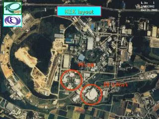
KEK layout
KEK layout. k. ito 1 JASS2002 Oct 21, 2002. PF-AR. PF-2.5GeV. N. k. ito 2 JASS2002 Oct 21, 2002. Layout of the Photon Factory. Synchrotron radiation beamlines in the vacuum ultraviolet and soft X-ray region. k. ito 3 JASS2002 Oct 21, 2002.

KEK layout
E N D
Presentation Transcript
KEK layout k. ito 1 JASS2002 Oct 21, 2002 PF-AR PF-2.5GeV N
k. ito 2 JASS2002 Oct 21, 2002 Layout of the Photon Factory
Synchrotron radiation beamlines in the vacuum ultraviolet and soft X-ray region k. ito 3 JASS2002 Oct 21, 2002 Kenji ITO e-mail: kenji.ito@kek.jpPhoton Factory, IMSS, KEK, Tsukuba, Ibaraki 305-0801, Japan Introduction Optical elements mirrors geometrical shape reflectivity grating basic understanding geometrical optics ray tracing varied-line spacing grating Monochromators normal incidence type grazing incidence type Summary
k. ito 4 JASS2002 Oct 21, 2002 What is the role of beamlines for SR usage? • conducting SR from the storage ring to the experimental stations 2) shaping SR beam, spatially and energetically, to meet the experimental requirements
Definition of VUV and SX k. ito 5 JASS2002 Oct 21, 2002 SiO2 1 mm 100 nm 10 nm 1 nm 0.1 nm Be IR VUV Soft X-rays 2a0 UV Extreme Ultraviolet Hard X-rays NK OK CK SiL SiK CuK 10 eV 10 keV 1 eV 100 eV 1 keV VUV: vacuum ultraviolet EUV: extreme ultraviolet SX: soft X-ray VUV-SX photons cannot propagate in the atmosphere!!! D. Attwood, “Soft X-rays and extreme ultraviolet radiation” (1999)
VUV-SX beamlines must be kept at k. ito 6 JASS2002 Oct 21, 2002 ultra-high vacuum (UHV) • To facilitate the propagation of the VUV-SX photons 2) Not to disturb the storage ring no mechanically-rigid window is available!!! 3) To protect the optical elements from contamination, oil-free primary pumps are recommended!!!
Layout of a typical beamline k. ito 7 JASS2002 Oct 21, 2002 branch-beam shutters shielding wall main beam-shutters Hutch X-ray Beamline SR VUV Beamline Interlock System pre-focusing mirror monochromator post-focusing mirror
Construction of a VUV-SX beamline k. ito 7 JASS2002 Oct 21, 2002 What kinds of measurements are required? Photon energy range Photon flux Beam size Photon band width Polarization Purity Coherence Beamline optics pre-focusing mirrors monochromator post-focusing mirrors Light source bending magnet undulator multipole wiggler This procedure does not work for a multipurpose beamline.
Optical elements used in the VUV-SX beamlines k. ito 9 JASS2002 Oct 21, 2002 1) reflection mirrors as a focussing tool 2) diffraction gratings, zone plates, multi- layered mirrors, filters and crystals as dispersion tools monochromators as a beamline system
Mirrors for SR use k. ito 10 JASS2002 Oct 21, 2002 1) focusing of VUV-SX light by various shapes of mirror: sphere, cylinder,parabola, paraboloid, ellipse, ellipsoid, toroid, etc • for better reflectivity in the VUV-SX region: • substrate: SiC, Si, SiO2, metal, other glass • coating materials: Au, Pt, Os,… with modern technology: 1-m long mirrors available surface roughness < 0.5 nm in rms slope error < 1 mrad beamspot size
k. ito 11 JASS2002 Oct 21, 2002 Aberration of spherical mirror Astigmatism of spherical mirror A Rowland circle O q q B C focussing plane Focusing mirrors of spherical shape
To avoid astigmatism: Focusing mirrors of toroidal shape k. Ito 12 JASS2002 Oct 21, 2002 source r r focus r´ sagittal R tangential
k. Ito 13 JASS2002 Oct 21, 2002 Parabolic mirrors to avoid aberration In 2D focusing: paraboloidal Y2=4aX a=f cos2q
k. Ito 14 JASS2002 Oct 21, 2002 F1 F2 (X/a)2+(Y/b) 2 =1 Elliptical mirrors to reduce aberration For 2D focusing: ellipsoidal shape mirrors
Reflectivity of mirrors k. Ito 15 JASS2002 Oct 21, 2002 Rs=Rp2 for 45° Complex refractive index Ñ = n - ik complex dielectric constant complex atomic scattering factor
Reflectivity of gold at 21.2 eV k. Ito 16 JASS2002 Oct 21, 2002 Brewster angle Rp=0 for dielectric material
k. Ito 17 JASS2002 Oct 21, 2002 Atomic scattering factor for Au Henke, Gullikson and Davis, Atomic Data and Neclear Data Tables, 54, 181 (1993)
Reflectivity of goldfor s-polarization k. Ito 18 JASS2002 Oct 21, 2002 L3 M5 N Mirrors can play the role of low pass filters. 1°=17.45 mrad Henke et al., Atomic and Nuclea Data Tables, 54, 181 (1993)
k. Ito 19 JASS2002 Oct 21, 2002 Surface roughness reduces the reflectivity • R=R0 exp[-(4ps sinf/l)2] • s : micro surface roughness in rms <0.5 nm • f: glancing angle
k. ito 20 JASS2002 Oct 21, 2002 Gratings as dispersion elements Diffraction grating Zone plate Multi-layered mirror Filters Crystals 1) Introduction 2) Efficiency 3) Geometrical optics ray tracing 4) Varied-line spacing grating
k. ito 21 JASS2002 Oct 21, 2002 a: amplitude of incident light I has maximal values for D=2mp. Equation for diffraction grating
k. ito 22 JASS2002 Oct 21, 2002 Focal plane q a r´ b f grating Dispersion of diffraction grating Angular dispersion: Reciprocal linear dispersion:
k. ito 23 JASS2002 Oct 21, 2002 m=1 m=0 m=2 m=-1 a incident light b m=-2 Diffraction efficiency m>0 positive order inside order m<0 negative order outside order Diffraction efficiency can be calculated by the scalar theory for l/d<<1. Rigorous numerical calculations based on Maxwell equations gives solutions with much better precision. Note that the efficiency strongly depends on the polarization of incident radiation.
k. ito 24 JASS2002 Oct 21, 2002 qb b a qb d Calculated by M. Neviere Blazed grating Maximal efficiency can be achieved at a-qb=qb-b. mlbK=2dsinqbcosK where blazed wavelength is lbK and deviation angle is 2K= a-b.
k. Ito 26 JASS2002 Oct 21, 2002 b a i q h d Laminar grating(1) • Grating equation • sina+sinb=ml/d • Efficiency • E0=100 cos2(d/2) • Em=(400/m2p2) sin2(d/2) • d=(2p/l)h(sini+sinq) • Primary maximum • /d=[2mcosi+(sinq)/p] ×(p2/4+m2) where P=h/d
k. ito 26 JASS2002 Oct 21, 2002 1 2 i q h Laminar grating(2) When the path difference between 1 and 2 is equal to l/2, destructive interference occurs. h(sini+sinq)= l/2 normal incidence: l=4h grazing incidence: l=2h(i+q) Suppression of 2nd order!!!
k. ito 27 JASS2002 Oct 21, 2002 Light path function F=AP+PB+nml Geometrical optics of diffraction gratings(1) Fermat’s principle: the pathlength of an actual ray traveling from a point A to a point B takes an extremal or stationary value. dF=0, where F is the pathlength from A to B. F: light path function The red ray meets the grating at a point P(x,w,l) on the nth groove, the zeroth groove being assumed to pass through O. Two rays diffracted from the zeroth and nth grooves are reinforced when their path difference is equal to nml.
k. ito 28 JASS2002 Oct 21, 2002 Geometrical optics of diffraction gratings(2) Expansion of F for z=0 and n=1/d spherical aberration astigmatism grating equation defocus in y-direction defocus in z-direction comma
k. ito 29 JASS2002 Oct 21, 2002 Rowland circle A r a b O r0´ B C Geometrical optics of diffraction gratings(3) Apply Fermat’s principle to F Roland mount r = R cosar0’ = R cosb0 F20=F30=0
k. ito 30 JASS2002 Oct 21, 2002 Geometrical optics of diffraction gratings(4) (L, M, N):direction cosine Ray-tracing (L´, M´, N´)
k. ito 31 JASS2002 Oct 21, 2002 Equation of image plane: where YZ-coordinate on S-plane Geometrical optics of diffraction gratings(5)
k. ito 32 JASS2002 Oct 21, 2002 S F SOURCE G S M M Geometrical optics of diffraction gratings(6) Spot diagram at exit slit By ray-tracing, it is possible to see 1) how the beam is focused on the slits and at F, 2) how it spreads on the grating, 3) the geometrical through-put.
k. ito 33 JASS2002 Oct 21, 2002 Geometrical optics of diffraction gratings(7) Analytical expression for spot diagrams Analytical merit function: Q Optimization of design parameters so as to minimize Q, where m is a weight function. Triple integrals have to be done over the grating surface. Note that Y and Z are dependent on li (i=1, 2, …N). Masui and Namioka, JOSA, 16, 2253 (1999)
k. ito 34 JASS2002 Oct 21, 2002 Geometrical optics of diffraction gratings(8) Hybrid design method : Koike and Namioka, JESRP, 80, 303 (1996) Ray-tracing of 18 rays determines fijk’s and gijk’s by solving simultaneous equations. Optimization process using the merit function in the same manner as before. Ray-tracing program is available at http://www.xraylith.wisc.edu/shadow/shadow.html
k. ito 35 JASS2002 Oct 21, 2002 sina+sinb=l/s s Varied line spacing gratings (1) Groove function Effective grating constant G=1 for mechanically ruled grating G=s/l0for holographic grating
k. ito 36 JASS2002 Oct 21, 2002 Varied line spacing gratings (2) HG´70 HG´90 Namioka and Koike, Appl. Opt., 34, 2180 (1995)
k. ito 37 JASS2002 Oct 21, 2002 Monochromators in the VUV-SX region for SR use (1) Normal incidence monochromators M. Koike, “Normal incidence monochromators and spectrometers” in J.A.R. Samson and D.L. Ederer Eds., “Vacuum Ultraviolet Spectroscopy II in Experimental Methods in Physical Sciences” Vol. 32, (Academic Press, New York, 1998, Chapter 1, pp. 1-20 review (A) Seya-Namioka type monochromator (B) Pseudo Rowland mount monochromator K. Ito, Y. Morioka, M. Ukai, N. Kouchi, Y. Hatano and T. Hayaishi, RSI, 66, 2119 (1995) (C) Eagle type monochromator 1) 6.65-m Eagle at BL-12B of the Photon Factory K. Ito, T. Namioka, Y. Morioka, T. Sasaki, H. Noda, K. Goto, T. Katayama and M. Koike,Appl. Opt., 25, 837-847 (1986) K. Ito and T. Namioka,Rev. Sci. Instr., 60, 1573-1578 (1989) K. Ito, K. Maeda, Y. Morioka and T. Namioka,Appl. Opt., 28, 1813-1817 (1989) 2) undulator based 6.65-m Eagle at BL9.02 of ALS M. Koike, P. Heimann, A. Kung, T. Namioka, R. DiGennaro, B. Gee and N. Yu, NIM, A347, 282 (1994) A.G. Suits, P. Heimann, X. Yang, M. Evans, C.W. Hsu, K. Lu, Y.T. Lee and A.H. Kung, RSI, 66, 4841 (1995) D.A. Mossessian, P. Heimann, E. Gullikson, R.K. Kaza, J. Chin and J. Arke, NIM, A347, 244 (1994) 3) 6.65-m Eagle with varibale polarization undulator at SU5 of LURE L. Nahon, B. Lagarde, F. Polack, C. Alcaraz, O. Dutuit, M. Vervloet and K. Ito,NIM, A404, 418-429 (1998) K. Ito, B. Lagarde, F. Polack, C. Alcaraz and L. Nahon,J. Synchrotron Rad., 5, 839-841 (1998) L. Nahon, C. Alcaraz, J-J. Marlats, B. Lagarde, F. Polack, R. Thissen, D. Lepere and K. Ito,RSI, 72, 1320 (2001)
k. ito 38 JASS2002 Oct 21, 2002 Seya-Namioka monochromator (1) R/r=1.220527 R/r’=1.216931 2K=69.44°
k. Ito 39 JASS2002 Oct 21, 2002 Seya-Namioka monochromator (2) 1000 rays, generated from the entrance slit 10mm long, hitting the 1800-grooves/mm grating with 100(W)60(H) mm2 : from Koike’s review conventional grating holographic grating recorded with a spherical wave front holographic grating recorded with an aspherical wave front E/DE3600 VLS grating with straight grooves E/DE3104 Through put: 23%
k. ito 40 JASS2002 Oct 21, 2002 Pseudo Rowland mount monochromator Robin-Romand mount toroidal mirror plane mirror toroidal mirror spherical grating of R=3m plane mirror K. Ito, Y. Morioka, M. Ukai, N. Kouchi, Y. Hatano and T. Hayaishi, RSI, 66, 2119 (1995)
k. ito 41 JASS2002 Oct 21, 2002 Dth is calculated by F20=0. r2 and d are chosen so that is minimized. Pseudo Rowland mount monochromator K. Ito, Y. Morioka, M. Ukai, N. Kouchi, Y. Hatano and T. Hayaishi, RSI, 66, 2119 (1995) With a 2400-l/mm grating, E/DE3104 can be attained.
k. ito 42 JASS2002 Oct 21, 2002 Off-plane Eagle (1) 6.65-m off-plane Eagle spectrograph installed at the PF in 1983
k. ito 43 JASS2002 Oct 21, 2002 Off-plane Eagle (2) 0.1nm 0.1nm Photographic Photoelectric
k. ito 44 JASS2002 Oct 21, 2002 Off-plane Eagle (3) Absorbed power density of M1 and M2 are 10.4 and 7.6 W/cm2. ALS M1: spherical M2: toroidal M4: cylindrical M5: cylindrical M6: toroidal Koike, Heimann, Kung, Namioka, DiGennaro, Gee and Yu, NIM, A347, 282 (1994)
k. ito 45 JASS2002 Oct 21, 2002 Off-plane Eagle (4) VUV high-resolution beamline with variable polarization at SU5 of SACO (LURE) With a 4300-l/mm grating, E/DE1.2105 can be attained. Nahon, Alcaraz, Marlats, Lagarde, Polack, Thissen, Lepere and K. Ito,RSI, 72, 1320 (2001)
k. ito 46 JASS2002 Oct 21, 2002 Monochromators in the VUV-SX region for SR use (2) Grazing incidence monochromators (A) Spherical grating monochromator (SGM) or Dragon C.T. Chen, NIM, A256, 595 (1987); C.T. Chen and F. Sette, RSI, 60, 1616 (1989). (B) SX700 (PGM, elliptical mirror) and modified SX700 H. Petersen, Opt. Com., 40, 402 (1982); H.A. Padmore, RSI, 60, 1608 (1989); H. Petersen et al., RSI, 66, 1777 (1995). (C) Monk-Gillieson type monochromator M. Hettrick et al., Appl. Opt., 27, 200 (1988); M. Koike and T. Namioka, RSI, 66, 2114 (1995). (D) Harada type monochromator (PGM) T. Harada, M. Itou and T. Kita, Proc. SPIE, 503, 114 (1984); M. Itou, T. Harada and T. Kita, Appl. Opt., 28, 146 (1989). (E) Grasshopper monochromator: Rowland mount F.C. Brown et al., NIM, 152, 73 (1978); F. Senf et al., RSI, 63, 1326 (1992).
k. ito 47 JASS2002 Oct 21, 2002 SGM at the BL-16B of the PF (1) Change the exit-slit position to satisfy the condition of F20=0 Shigemasa et al., JSR, 5, 772 (1998)
k. ito 48 JASS2002 Oct 21, 2002 N2 Theoretical estimation for resolving power Ar SGM at the BL-16B of the PF (2) Shigemasa et al., JSR, 5, 772 (1998)
k. ito 49 JASS2002 Oct 21, 2002 F20=0 with R= C=2.25 high grating efficiency rotation tilting or rotation+translation SX-700 H. Petersen, Opt. Com., 40, 402 (1982)
k. ito 50 JASS2002 Oct 21, 2002 Modified SX-700on-blaze type monochromator Padmore, RSI, 60, 1608 (1989); Petersen et al., RSI, 66, 1777 (1995). M. Fijuisawa, private communication