Intro to AVR ATtiny2313
160 likes | 310 Vues
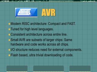
CS423 Dick Steflik. Intro to AVR ATtiny2313. AVR ATtiny2313. 2313 Features. RISC, 120 instructions, most executable in one clock cycle, 32x8 general purpose registers, up to 20 MIPS at 20 Mhz Memory - 2Kbytes Flash, 128 Bytes EEPROM, 128 bytes SRAM

Intro to AVR ATtiny2313
E N D
Presentation Transcript
CS423 Dick Steflik Intro to AVR ATtiny2313
2313 Features • RISC, 120 instructions, most executable in one clock cycle, 32x8 general purpose registers, up to 20 MIPS at 20 Mhz • Memory - 2Kbytes Flash, 128 Bytes EEPROM, 128 bytes SRAM • Peripherals Features – 1-8bit timer, 1- 16 bit timer, 4- PWM channels, On-chip analog comparitor, watchdog timer, Universal Serial Interface, Full Duplex USART • 18 programmable I/O lines • Operating Voltage – 2.7 – 5.5VDC • In System Programmable via SPI (Serial Peripheral Interface)
Basic Pin Descriptions • VCC – Digital Supply Voltage • Gnd – ground • Port A (PA2..PA0) – 3 bit, bi-directional I/O with selectable internal pullups • Port B (PB7..PB0) – 8 bit, bi-directional I/O with selectable internal pullups • Port D (PD6-PD0) - 7 bit, bi-directional I/O with selectable internal pullups • Reset – system reset – active low • XTAL1 – external crystal input (alt. PA0) • XTAL2 – external crystal output (alt. PA1)
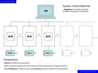
Serial Peripheral Interface Bus • SPI is used by all Atmel microcontrollers for loading the flash program memory (many other OEMs also) • Easily implemented in hardware • Faster than other methods (I2C, SMBUS) • Master-slave methodology • Half or Full Duplex operation
SPI with 2 slaves SPI Master SPI Slave 1 SCLK SCLK MOSI MOSI MISO MISO SS1 SS SS2 SPI Slave 2 SCLK MOSI MISO SS
AVR Programming AVR Programmer ATtiny2313 PC VCC (20) VCC SCLK (19) SCLK MOSI MOSI (17) AVRDUDE MISO MISO (18) PPT RS232 USB RESET (1) GND GND (10) GND
API Applications • Flash, EEPROM, MMC and SD cards • Sensors • Temperature • Pressure (touch screens) • LCD Panels • Communications (802.15 (ZigBee), CAN, Ethernet....) • Control – D/A, A/D, Digital Pots, position encoders
/* Blinker Demo */ /* Include useful pre-defined functions */ #include <avr/interrupt.h> // Defines pins, ports, etc to make programs easier to read #define F_CPU 100000UL // Sets up the default speed for delay.h #include <util/delay.h> int main(){ DDRD = _BV(PD4); /* enable output on port D, pin 4 */ while(1){ PORTD = _BV(PD4); _delay_ms(1000); PORTD &= ~_BV(PD4); _delay_ms(1000); } return(0); }
Interrupts 1 0x0000 Reset External Pin, POR, BOR,Watchdog Reset 2 0x0001 INT0 External Interrupt Request 0 3 0x0002 INT1 External Interrupt Request 1 4 0x0003 TIMER1 CAPT Timer/Counter1 Capture Event 5 0x0004 TIMER1 COMPA Timer/Counter1 Compare Match A 6 0x0005 TIMER1 OVF Timer/Counter1 Overflow 7 0x0006 TIMER0 OVF Timer/Counter0 Overflow 8 0x0007 USART0,RX USART0 Receive complete 9 0x0008 USART0 UDRE USART0 Data Register Empty 10 0x0009 USART0 RX USART0 Transmit Complete 11 0x000A ANALOG COMP Analog Comparitor 12 0x000B PCINT Pin Change Interrupt 13 0x000C TIMER1 COMPB Timer/Counter1 Compare Match B 14 0x000D TIMER0 COMPA Timer/Counter0 Compare Match A 15 0x000E TIMER0 COMPB Timer/Counter0 Compare Match B 16 0x000F USI START USI Start Condition 17 0x0010 USI OVERFLOW USI Overflow 18 0x0011 EE READY EEPROM Ready 19 0x0012 WDT OVERFLOW Watchdog Timer Overflow
ISR Macro • #include <avr/interrupt.h> • Defines the beginning of your Interrupt Servicing Routine • Places the starting address of the ISR code into the interrupt vector ISR(SIG_INT0) { cli(); //disable interrupts . . . sei(); // enable interrupts } places address of the body if the ISR into 0x0001
Programmable Interrupts • INT0 - Pin 6 • INT1 – Pin 7 • PCINT – Pins 12-19 • PCMSK – Pin Change Mask Register • Which pins contribute to the pin change interrupt • 4 different pin changes can be detected • Pin goes low • Any logical change • Falling edge • Rising edge
Interrupt Sense Control Interrupt 1 Sense Control ISC11 ISC10 Description 0 0 Low level on INT1 0 1 Any logical change on INT1 1 0 Falling edge on INT1 1 1 Rising Edge on INT1 Interrupt 0 Sense Control ISC01 ISC00 Description 0 0 Low level on INT0 0 1 Any logical change on INT0 1 0 Falling edge on INT0 1 1 Rising Edge on INT0
MCU Control Register • Defines which of the four states will activate the interrupt ex. MCUCR = (1<<ISC01) | (1<<ISC00) Interrupt on pin INT0 falling edge
Example #include <avr/interrupt.h> int main(void) { // set Pin 6 (PD02) as the interrupt pin PCMSK |= (1<<PIND2); // interrupt on INT0 falling edge MCUCR = (1<<ISC01) | (1 << ISC00); // turn on interrupts GIMSK |= (1<<INT0); // wait for interrupt while (1) { ... };