Practical Temperature Measurements
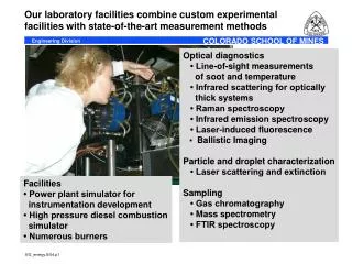
This classroom series from Agilent Technologies delves into the essential aspects of temperature measurement. It covers the historical background of temperature sensing, describes various sensors including mechanical, electrical, optical pyrometers, RTD (Resistance Temperature Detector), thermistors, and thermocouples. The agenda addresses how heat is transferred through conduction, convection, and radiation, and discusses the importance of calibration and accuracy in temperature measurements. Participants will gain a comprehensive understanding of theoretical concepts and practical applications of temperature sensors.


Practical Temperature Measurements
E N D
Presentation Transcript
Agilent Technologies Classroom Series Practical Temperature Measurements 001
Agenda • Background, history • Mechanical sensors • Electrical sensors • Optical Pyrometer • RTD • Thermistor, IC • Thermocouple • Summary & Examples A1
What is Temperature? • A scalar quantity that determines the direction of heat flow between two bodies • A statistical measurement • A difficult measurement • A mostly empirical measurement 002
How is heat transferred? • Conduction 003 • Metal coffee cup • Convection • Radiation
The Dewar 004 • Glass is a poor conductor • Gap reduces conduction • Metallization reflects radiation • Vacuum reduces convection
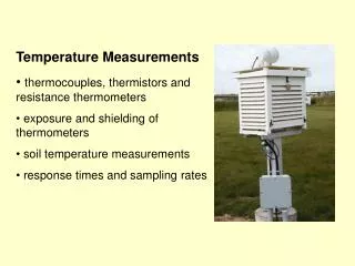
Sensor Sensor Thermal Mass 005 • Don't let the measuring device change the temperature of what you're measuring. • Response time = • f{Thermal mass} • f{Measuring device}
Temperature errors • What is YOUR normal temperature? • Thermometer accuracy, resolution • Contact time • Thermal mass of thermometer, tongue • Human error in reading 006 97.6 98.6 99.6 36.5 37 37.5
96 12 1 0 History of temperature sensors • 1600 ad • 1700 ad 007 • Fahrenheit • Instrument Maker • 12*8=96 points • Hg: Repeatable • One standard scale • Galileo: First temp. sensor • pressure-sensitive • not repeatable • Early thermometers • Not repeatable • No good way to calibrate
0 100 100 0 The 1700's: Standardization • 1700 ad • 1800 ad 008 • Thomson effect • Absolute zero • Celsius: • Common, repeatable calibration reference points • "Centigrade" scale
d 1821: It was a very good year • 1800 ad • 1900 ad 009 • The Seebeck effect • Davy: The RTD • Pt 100 @ O deg.C
The 1900's: Electronic sensors • 1900 ad • 2000 ad 010 • 1 uA/K • Thermistor • IC sensor • IPTS 1990 • IPTS 1968 • "Degree Kelvin">> "kelvins" • "Centigrade">> " Celsius"
Freezing point H O Boiling point H O 2 2 Temperature scales Absolute zero 011 • Celsius 100 0 -273.15 • Kelvin 0 273.15 373.15 • Fahrenheit 32 212 -459.67 • Rankine 671.67 0 427.67 • "Standard" is "better": • Reliable reference points • Easy to understand
IPTS '90: More calibration points • 1357.77: FP Cu • 273.16: TP H2O • 234.3156: TP Hg 012 • 1337.33: FP Au • 1234.93: FP Ag Large gap • 933.473: FP Al • 692.677: FP Zn • 83.8058: TP Ar • 505.078: FP Sn • 54.3584: TP O2 • 429.7485: FP In • 24.5561: TP Ne • 20.3: BP H2 • 17 Liq/vapor H2 • 302.9146: MP Ga • 13.81 TP H2 • 3 to 5: Vapor He
Agenda • Background, history • Mechanical sensors • Electrical sensors • Optical Pyrometer • RTD • Thermistor, IC • Thermocouple • Summary & Examples A2
200 100 300 0 400 Bimetal thermometer • Forces due to thermal expansion • Two dissimilar metals, tightly bonded 013 • Result • Bimetallic thermometer • Poor accuracy • Hysteresis • Thermal expansion causes big problems in other designs: • IC bonds • Mechanical interference
100 0 Liquid thermometer; Paints 014 • Thermally-sensitive paints • Irreversible change • Low resolution • Useful in hard-to-measure areas • Liquid-filled thermometer • Accurate over a small range • Accuracy & resolution= f(length) • Range limited by liquid • Fragile • Large thermal mass • Slow
Agenda • Background, history • Mechanical sensors • Electrical sensors • Optical Pyrometer • RTD • Thermistor, IC • Thermocouple • Summary & Examples A3
Optical Pyrometer 015 • Infrared Radiation-sensitive • Photodiode or photoresistor • Accuracy= f{emissivity} • Useful @ very high temperatures • Non-contacting • Very expensive • Not very accurate
Agenda • Background, history • Mechanical sensors • Electrical sensors • Optical Pyrometer • RTD • Thermistor, IC • Thermocouple • Summary & Examples A4
Resistance Temperature Detector 016 • Most accurate & stable • Good to 800 degrees Celsius • Resistance= f{Absolute T} • Self-heating a problem • Low resistance • Nonlinear
RTD Equation • R= 100 Ohms @ O C • Callendar-Van Deusen Equation: • R=Ro(1+aT) - Ro(ad(.01T)(.01T-1)) • Ro=100 @ O C • a= 0.00385 / - C • d= 1.49 For T>OC: for Pt R 300 200 100 Nonlinearity T • 0 200 400 600 800 017
d Measuring an RTD: 2-wire method Rlead Rx + 100 V I ref= 5 mA d Rlead Pt - • R= Iref*(Rx + 2* Rlead) • Error= 2 /.385= more than 5 degrees C for 1 ohm Rlead! • Self-heating: • For 0.5 V signal, I= 5mA; P=.5*.005=2.5 mwatts • @ 1 mW/deg C, Error = 2.5 deg C! • Moral: Minimize Iref; Use 4-wire method • If you must use 2-wire, NULL out the lead resistance 018
d d The 4-Wire technique Rx + 100 V 019 Rlead=1 I ref= 5 mA - • R= Iref * Rx • Error not a function of R in source or sense leads • No error due to changes in lead R • Twice as much wire • Twice as many scanner channels • Usually slower than 2-wire
d Offset compensation Voffset + 020 100 V I ref (switched) - • Eliminates thermal voltages • Measure V without I applied • Measure V I applied With V R= I
d 100 1000 d V d 1000 d Bridge method 021 100 • High resolution (DMM stays on most sensitive range) • Nonlinear output • Bridge resistors too close to heat source
d d V d d 3-Wire bridge 100 1000 Rlead 1 022 3-Wire PRTD Sense wire 1000 Rlead 2 100 • Keeps bridge away from heat source • Break DMM lead (dashed line); connect to RTD through 3rd "sense" wire • If Rlead 1= Rlead 2, sense wire makes error small • Series resistance of sense wire causes no error
Agenda A5 • Background, history • Mechanical sensors • Electrical sensors • Optical Pyrometer • RTD • Thermistor, IC • Thermocouple • Summary & Examples
d d d d d Electrical sensors: Thermistor Rlead=1 + V 5k I= 0.1 mA • Hi-Z; Sensitive: 5 k @ 25C; R = 4%/deg C Rlead=1 - • Limited range • 2-Wire method: R= I * (Rthmr + 2*Rlead) • Lead R Error= 2 /400= 0.005 degrees C • Low thermal mass: High self-heating • Very nonlinear 023
d V I.C. Sensor d AD590 I= 1 uA/K • High output • Very linear • Accurate @ room ambient • Limited range • Cheap + 100 - 5V = 1mV/K 960 024
I.C. AD590 RTD Thermistor • High output • Fast • 2-wire meas. • High output • Most linear • Inexpensive • Most accurate • Most stable • Fairly linear • Very nonlinear • Limited range • Needs I source • Self-heating • Fragile • Expensive • Slow • Needs I source • Self-heating • 4-wire meas. • Limited variety • Limited range • Needs V source • Self-heating Summary: Absolute T devices 025
Agenda • Background, history • Mechanical sensors • Electrical sensors • Optical Pyrometer • RTD • Thermistor, IC • Thermocouple • Summary & Examples A6
Ta Tx V Tx V= e(T) dT Ta Thermocouples The Gradient Theory 026 • The WIRE is the sensor, not the junction • The Seebeck coefficient (e) is a function of temperature
Ta Tx B V A Ta Tx V= e dT Ta Making a thermocouple 027 • Two wires make a thermocouple • Voltage output is nonzero if metals are not the same Ta + e dT B A Tx
Ta Tx A V A Ta Tx V= e dT Ta Gradient theory also says... 028 • If wires are the same type, or if there is one wire, and both ends are at the same temperature, output= Zero. Ta + e dT = 0 A A Tx
a Fe Tx b Con Fe Cu Cu Fe = Tx Tx V V Con Cu Con Cu Now try to measure it: • Theoretically, Vab= f{Tx-Tab} • Result: 3 unequal junctions, all at unknown temperatures • But, try to measure it with a DMM: 029
Fe Cu Cu Fe Tx Add Tx Con V Con V Tref = 0 C Tref o Cu Fe Cu Fe Solution: Reference Thermocouple • Problems: a) 3 different thermocouples, b) 3 unknown temperatures 030 • Solutions: a) Add an opposing thermocouple b) Use a known reference temp. Isothermal block
The Classical Method Cu Fe 031 • If both Cu junctions are at same T, the two "batteries" cancel • Tref is an ice bath (sometimes an electronic ice bath) • All T/C tables are referenced to an ice bath • V= f{Tx-Tref} Tx Con V Tref = 0 C o Cu Fe • Question: How can we eliminate the ice bath?
Fe Cu Tx Con V Cu Fe Eliminating the ice bath • Don't force Tref to icepoint, just measure it • Compensate for Tref mathematically:V=f{ Tx - Tref } • If we know Tref , we can compute Tx. 032 Tice Tref Tice Tice
Fe Cu Tx Con V Cu Fe Eliminating the second T/C 033 • Extend the isothermal block • If isothermal, V1-V2=0 2 Fe Cu Tref Tx V Tref Con 1 2 Cu 1
Fe Cu Tx Tref V Con Cu The Algorithm for one T/C • Measure Tref: RTD, IC or thermistor • Tref ==> Vref @ O C for Type J(Fe-C) • Know V, Know Vref: Compute Vx • Solve for using Vx o Tx Compute Vx=V+Vref Vx V Vref Tx Tref 0 o 034
Linearization V 035 Small sectors T Tx Tref 0 o 2 9 3 • Polynomial: T=a +a V +a V +a V +.... a V • Nested (faster): T=a +V(a +V(a +V(a +.......))))))))) • Small sectors (faster): T=T +bV+cV • Lookup table: Fastest, most memory 0 1 2 3 9 0 1 2 3 2 0
mV E E E 60 K J N 40 20 R T S deg C 0 500 1000 2000 Common Thermocouples 036 Platinum T/Cs Base Metal T/Cs • All have Seebeck coefficients in MICROvolts/deg.C
Common Thermocouples Seebeck Coeff: uV/C 037 Type Metals • Microvolt output is a tough measurement • Type "N" is fairly new.. more rugged and higher temp. than type K, but still cheap Fe-Con Ni-Cr Cu-Con Pt/Rh-Pt Ni/Cr-Con Ni/Cr/Si-Ni/Si 50 40 38 10 59 39 J K T S E N
Extension Wires • Possible problemhere 038 Large extension wires Small diametermeasurementwires • Extension wires are cheaper, more rugged, but not exactly the same characteristic curve as the T/C. • Keep extension/TC junction near room temperature • Where is most of the signal generated in this circuit?
Normal Mode ac NOISE HI DMM Normal Mode Input LO Resistance dc SIGNAL HI DMM Input Resistance LO Common Mode ac NOISE Noise: DMM Glossary 039 • Normal Mode: In series with input • Common Mode: Both HI and LOterminals driven equally
Electrostatic Noise Magnetic Noise HI DMM Input LO Resistance dc SIGNAL HI DMM Input R lead Resistance LO R leak Common Mode ac source Common Mode Current Generating noise 040 Normal Mode • Large surface area, high Rlead: Max. static coupling • Large loop area: Max. magnetic coupling • Large R lead, small R leak: Max.common mode noise
Electrostatic Noise Magnetic Noise HI DMM Input LO R HI DMM Input R - + LO R leak Common Mode ac source Common Mode Current Eliminating noise 041 Normal Mode dc SIGNAL • Filter, shielding, small loop area(Caution: filter slows down the measurement) • Make R leak close to
Magnetic Noise • Magnetic coupling 042 DMM InputResistance Induced I • Minimize area • Twist leads • Move away from strong fields
Reducing Magnetic Noise • Equal and opposite induced currents 043 DMM InputResistance • Even with twisted pair: • Minimize area • Move away from strong fields
Electrostatic noise AC Noise source 044 Stray capacitances DMM InputResistance Inoise Stray resistances • Stray capacitance causes I noise • DMM resistance to ground is important