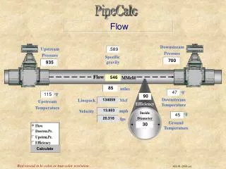
Upstream Tracker Data Format
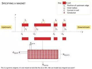
Upstream Tracker Data Format. JC Wang Upgrade Electronics & AMC40 Firmware Meeting 12/12/2013. UT - Upstream Tracker. 1731 mm. UT detector consists of 4 planes at Z locations similar to that of TT. The middle two planes are at ±5 .

Upstream Tracker Data Format
E N D
Presentation Transcript
Upstream Tracker Data Format JCWang Upgrade Electronics & AMC40 Firmware Meeting 12/12/2013
UT - Upstream Tracker 1731 mm • UT detector consists of 4 planes at Z locations similar to that of TT. The middle two planes are at ±5. • Each plane has 16 or 18 modules stretching from top to bottom. • There are 14 or 16 sensors per module mounted on both sides alternatively for overlaps. • Strips of UT sensor are vertical, pitch=190, 95 mm, length=5,10 cm. • Analog signals are digitized by SALT ASICs at the sensor proximity. Each ASIC handles128 strips. • Digital data are sent to the ends of modules via flex data cable as and further via optical fiber. • In total there are 68 modules, 968 sensors, and 4192 ASICs. UTbX UTbV UTaU UTaX 66.8 mm 1346 mm 315 mm 1538 mm
Readout Chain DCB DCB Hybrid AMC40 Flex ASICs AMC40 AMC40 Sensor Kapton cable for Data/Power Versatile links @ 4.48 Gbps or 3.2 Gbps Module Stave for cooling & support E-links @ 320 Mbps UT hybrid • UT signals from silicon strips are digitized and zero suppressed at ASICs, 4 or 8 ASICs per sensor. • Digital data are sent to data concentrator boards (DCB) via e-link lines in flex data cable as SLVS signals. • UT e-ports/e-links operates at 320 Mbps. One ASIC needs up to 5 e-links, depending on the occupancy. • DCBs pack data from up to 10 or 14 e-links passively to GBTx frame and send to AMC40 via optical fibers. Data concentrator boards DCB DCB
Data Format @ ASIC • UT data format was formed with help from Federico Alessio. This is an optimized revision during implementation in the SALT chip. • Events of all BXIDs are saved, in sequential BXID order. The length of BXID is 4-bit. • For high probability BXVeto & empty event (no hit in ASIC), only the 6-bits header is sent. • For events that NumHits 63, a 6-bit “Length” is used for the number of hits that follow. Each hit is a 12-bit data (7 for channel ID, 5 for ADC). • If NumHits > 63, or the buffer is full, a truncated event packet is saved instead. Length = NumHits/4 is saved for monitor purpose. No actual hit data follows. The default truncation threshold is 63, which is configurable and can be tightened if necessary. • When there is not enough data to fill all e-ports, one or more idle packets are added. • UT does not mix NZS & ZS data. NZS is for calibration or test run only. Its packet header is unique. The length of data that follow = 804 bits. Details can be found in appendix.
UT GBTx Packet Format = 80 or 112 From “Electronics Architecture of the LHCb Upgrade” http://cds.cern.ch/record/1340939 UT ASICs are independent. E-ports within an ASIC send data coherently as if they are from one port. Each ASIC data form its own GBT sub-frame. head0 data00000000000000000000000 head0 data00000 head0 000000 00000000000000000 head1 head idle 00000000000000000000 111111 idle head2 data222222222222222222222222 00000000 head1 data head2 2222222222222222222222222222222222222222 11111111111111111 idle Up to 10 or 14 e-ports for passive DCB
AMC40 Resource Issue And Possible Options • In the initial design DCB packs events passively. Each ASIC occupies a fixed number of bits in the GBTx frame (a sub-frame). The sub-frames are independent. • AMC40 FPGA does not have enough resource to handle 24 x multi-sub-frames, as found by Guillaume Vouters. • We are exploring two options: repacking at DCB, or keep passive DCB, and do something at AMC40 end. • Repacking: To repack data at DCB we need FPGAs to decode, BXID align and pack event, just like what is done at AMC40. The FPGA needs to work in a radiation environment (up to 10-30 kRad). There are ~1000 GBT to handle. • Passive: On AMC40 side we plan to match ASICs according to their occupancy etc. So different AMC40 can be optimized for different issues, e.g. long waiting or more sub-frames; More AMC40 may be used to reduce number of sub-frames per board, and we use 80 bit GBT frame width; More powerful FPGA is also possible. • We are still investigating. Feasibility, cost and data integrity are the factors that we need to consider.
UT Data Format for DCB - AMC40 • If we choose to repack events at DCB, this is the format of data sent to AMC40. • Up to 8 ASICs are repacked into one GBTx frame, no sub-frame in it. • All headers have fixed length = 24 bits. Header fields are protected by 7-bit error detection & correction (EDAC) information. • Each hit needs 15 bits ( 3 + 7 for channel ID, 5 for ADC). We use 16 bits instead to have header aligned with bytes. This helps at AMC40. • When there isn’t sufficient data to send, DCB sends an all-zero GBT frame, which may insert inside an event. This is consistent with the general specification.
Miscellaneous Other Information (I) • Front end contacts: Krzysztof Swientek. • Technology: ASIC (passive DCB), ASIC+FPGA (repacking). • Data format information (not already presented): • GBT width: 80 for passive, 112 for repacking as UT has its own header correction. • NZS possible: NZS for calibration or special runs only. No ZS & NZS mixing run. • Without repacking, in each sub-frame the max ZS data after one header is 63*12 = 756 bits, NZS data has fixed size 804 bits. With repacking, in each frame the max ZS data after one header is 8*63* 16 = 8064 bits, max NZS data has 6404 bits. • Are data time-ordered by BXID: Data are time ordered. All BXIDs are saved. • Data format compliant with the specs: For passive DCB solution data from 4192 ASICs are not synchronized. Each ASIC occupies a sub-frame. • UT hit clustering & spill-over correction will be done on AMC40. • Sync command integration & synch-frame definition: not settled yet. • Data latency to AMC40 is not fixed. • For passive DCB, data contains idle packets that should be ignore. It has unique header flags. For repacking solution, standard idle frame will be sent.
Miscellaneous Other Information (II) • Special run modes: We need NZS runs for pedestal/noise & test pulse calibration, low intensity beam test run for debugging purpose. • Data emulation available: ASIC DSP design and simulation is in progress; We have simulated output of e-ports and DCB gbtx from MC data as input to AMC40. • Estimated bandwidth: ~1000-1200 GBTx links, ~ 40-50 AMC40. • Estimation resources FE encoding: working on it. • Bit ordering: MSB first. • Back end contact: Jianchun Wang. • Data processing: with UT-specific functions adding to generic firmware. Status: infrastructure setup ready (mini-DAQ, work station). We have C++ simulation of readout chain and UT-specific functions using MC data. • Output interface ?? • DSP block is needed to add UT-specific functions, including spill over correction and hit clustering.
Data Format @ ASIC (Rev. I) • Event is truncated if NumHits>Threshold or buffer is full. The threshold is configurable. Length=NumHitsfor monitor purpose, although no hit follows. • Hit data 12-bit = 7-bit channel ID + 5-bit ADC. • Header length shorter for high probability type of events. • DSP implementation may require re-optimization.
NZS UT Data Format • In pedestal/noise, test pulse or other special test runs UT can be in non-zero-suppression (NZS) mode. • All 6-bit ADC values without pedestal subtraction are sent out channel by channel in sequential channel ID order.No channel ID is needed. • We also want to save a few parameters in digital process for debugging purpose. The number may increase when digital process is finalized: • The event data size is fixed (4 + 8 + 4 + 4x8+128x6 = 816 bits).