Download
1 / 42
760 likes | 1.51k Vues
CH NO. 6 FUNDAMENTALS OF WELDING. Overview of Welding Technology The Weld Joint Physics of Welding Features of a Fusion Welded Joint. Joining and Assembly Distinguished. Joining – welding and adhesive bonding These processes form a permanent joint between parts

E N D
CH NO. 6FUNDAMENTALS OF WELDING • Overview of Welding Technology • The Weld Joint • Physics of Welding • Features of a Fusion Welded Joint ©2010 John Wiley & Sons, Inc. M P Groover, Principals of Modern Manufacturing 4/e SI Version
Joining and Assembly Distinguished Joining – welding and adhesive bonding • These processes form a permanent joint between parts Assembly - mechanical methods (usually) of fastening parts together • Some of these methods allow for easy disassembly, while others do not ©2010 John Wiley & Sons, Inc. M P Groover, Principals of Modern Manufacturing 4/e SI Version
Welding Joining process in which two (or more) parts are coalesced at their contacting surfaces by application of heat and/or pressure • Many welding processes are accomplished by heat alone, with no pressure applied • Others by a combination of heat and pressure • Still others by pressure alone with no external heat • In some welding processes a filler material is added to facilitate coalescence ©2010 John Wiley & Sons, Inc. M P Groover, Principals of Modern Manufacturing 4/e SI Version
Why Welding is Important • Provides a permanent joint • Welded components become a single entity • Usually the most economical way to join parts in terms of material usage and fabrication costs • Mechanical fastening usually requires additional hardware (e.g., screws) and geometric alterations of the assembled parts (e.g., holes) • Not restricted to a factory environment • Welding can be accomplished "in the field" ©2010 John Wiley & Sons, Inc. M P Groover, Principals of Modern Manufacturing 4/e SI Version
Limitations and Drawbacks of Welding • Most welding operations are performed manually and are expensive in terms of labor cost • Most welding processes utilize high energy and are inherently dangerous • Welded joints do not allow for convenient disassembly • Welded joints can have quality defects that are difficult to detect ©2010 John Wiley & Sons, Inc. M P Groover, Principals of Modern Manufacturing 4/e SI Version
Types of Welding Processes • Some 50 different types of welding processes have been catalogued by the American Welding Society (AWS) • Welding processes can be divided into two major categories: • Fusion welding • Solid state welding ©2010 John Wiley & Sons, Inc. M P Groover, Principals of Modern Manufacturing 4/e SI Version
Fusion Welding Joining processes that melt the base metals • In many fusion welding operations, a filler metal is added to the molten pool to facilitate the process and provide bulk and added strength to the welded joint • A fusion welding operation in which no filler metal is added is called an autogenous weld ©2010 John Wiley & Sons, Inc. M P Groover, Principals of Modern Manufacturing 4/e SI Version
Some Fusion Welding Processes • Arc welding (AW) – melting of the metals is accomplished by an electric arc • Resistance welding (RW) ‑ melting is accomplished by heat from resistance to an electrical current between faying surfaces held together under pressure • Oxyfuel gas welding (OFW) ‑ melting is accomplished by an oxyfuel gas such as acetylene ©2010 John Wiley & Sons, Inc. M P Groover, Principals of Modern Manufacturing 4/e SI Version
Arc Welding • Basics of arc welding: (1) before the weld; (2) during the weld, the base metal is melted and filler metal is added to molten pool; and (3) the completed weldment ©2010 John Wiley & Sons, Inc. M P Groover, Principals of Modern Manufacturing 4/e SI Version
Solid State Welding Joining processes in which coalescence results from application of pressure alone or a combination of heat and pressure • If heat is used, temperature is below melting point of metals being welded • No filler metal is added in solid state welding ©2010 John Wiley & Sons, Inc. M P Groover, Principals of Modern Manufacturing 4/e SI Version
Some Solid State Welding Processes • Diffusion welding (DFW) –coalescence is by solid state fusion between two surfaces held together under pressure at elevated temperature • Friction welding (FRW) ‑ coalescence by heat of friction between two surfaces • Ultrasonic welding (USW) ‑ coalescence by ultrasonic oscillating motion in a direction parallel to contacting surfaces of two parts held together under pressure ©2010 John Wiley & Sons, Inc. M P Groover, Principals of Modern Manufacturing 4/e SI Version
Principal Applications of Welding • Construction - buildings and bridges • Piping, pressure vessels, boilers, and storage tanks • Shipbuilding • Aircraft and aerospace • Automotive • Railroad ©2010 John Wiley & Sons, Inc. M P Groover, Principals of Modern Manufacturing 4/e SI Version
Welder and Fitter • The welder manually controls the path or placement of welding gun • Often assisted by second worker, called a fitter, who arranges the parts prior to welding • Welding fixtures and positioners are used to assist in this function ©2010 John Wiley & Sons, Inc. M P Groover, Principals of Modern Manufacturing 4/e SI Version
The Safety Issue • Welding is inherently dangerous to human workers • High temperatures of molten metals • In gas welding, fuels (e.g., acetylene) are a fire hazard • Many welding processes use electrical power, so electrical shock is a hazard ©2010 John Wiley & Sons, Inc. M P Groover, Principals of Modern Manufacturing 4/e SI Version
Special Hazards in Arc Welding • Ultraviolet radiation emitted in arc welding is injurious to human vision • Welder must wear special helmet with dark viewing window • Filters out dangerous radiation but welder is blind except when arc is struck • Sparks, spatters of molten metal, smoke, and fumes • Ventilation needed to exhaust dangerous fumes from fluxes and molten metals ©2010 John Wiley & Sons, Inc. M P Groover, Principals of Modern Manufacturing 4/e SI Version
Arc Welding • A manual arc welding operation • Welder must wear protective clothing and helmet ©2010 John Wiley & Sons, Inc. M P Groover, Principals of Modern Manufacturing 4/e SI Version
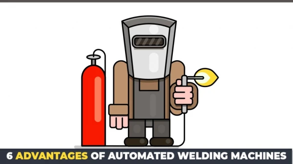
Automation in Welding • Because of the hazards of manual welding, and to increase productivity and improve quality, various forms of mechanization and automation are used • Machine welding – mechanized welding under supervision and control of human operator • Automatic welding – equipment performs welding without operator control • Robotic welding - automatic welding implemented by industrial robot ©2010 John Wiley & Sons, Inc. M P Groover, Principals of Modern Manufacturing 4/e SI Version
The Weld Joint The junction of the edges or surfaces of parts that have been joined by welding • Two issues about weld joints: • Types of joints • Types of welds used to join the pieces that form the joints ©2010 John Wiley & Sons, Inc. M P Groover, Principals of Modern Manufacturing 4/e SI Version
Five Types of Joints (a) Butt joint, (b) corner joint, (c) lap joint, (d) tee joint, and (e) edge joint ©2010 John Wiley & Sons, Inc. M P Groover, Principals of Modern Manufacturing 4/e SI Version
Types of Welds • Each of the preceding joints can be made by welding • Other joining processes can also be used for some of the joint types • There is a difference between joint type and the way it is welded ‑ the weld type ©2010 John Wiley & Sons, Inc. M P Groover, Principals of Modern Manufacturing 4/e SI Version
Fillet Weld • Used to fill in the edges of plates created by corner, lap, and tee joints • Filler metal used to provide cross section in approximate shape of a right triangle • Most common weld type in arc and oxyfuel welding • Requires minimum edge preparation ©2010 John Wiley & Sons, Inc. M P Groover, Principals of Modern Manufacturing 4/e SI Version
Fillet Welds • (a) Inside single fillet corner joint; (b) outside single fillet corner joint; (c) double fillet lap joint; (d) double fillet tee joint (dashed lines show the original part edges) ©2010 John Wiley & Sons, Inc. M P Groover, Principals of Modern Manufacturing 4/e SI Version
Groove Welds • Usually requires part edges to be shaped into a groove to facilitate weld penetration • Edge preparation increases cost of parts fabrication • Grooved shapes include square, bevel, V, U, and J, in single or double sides • Most closely associated with butt joints ©2010 John Wiley & Sons, Inc. M P Groover, Principals of Modern Manufacturing 4/e SI Version
Groove Welds • (a) Square groove weld, one side; (b) single bevel groove weld; (c) single V‑groove weld; (d) single U‑groove weld; (e) single J‑groove weld; (f) double V‑groove weld for thicker sections (dashed lines show original part edges) ©2010 John Wiley & Sons, Inc. M P Groover, Principals of Modern Manufacturing 4/e SI Version
Plug Weld and Slot Weld • (a) Plug weld and (b) slot weld ©2010 John Wiley & Sons, Inc. M P Groover, Principals of Modern Manufacturing 4/e SI Version
Spot Weld and Seam Weld Fused section between surfaces of two sheets or plates: (a) spot weld and (b) seam weld • Used for lap joints • Closely associated with resistance welding ©2010 John Wiley & Sons, Inc. M P Groover, Principals of Modern Manufacturing 4/e SI Version
Flange Weld and Surfacing Weld • (a) Flange weld and (b) surfacing weld used not to join parts but to deposit filler metal onto surface of a base part ©2010 John Wiley & Sons, Inc. M P Groover, Principals of Modern Manufacturing 4/e SI Version
Physics of Welding • Fusion is most common means of achieving coalescence in welding • To accomplish fusion, a source of high density heat energy must be supplied to the faying surfaces • Resulting temperatures cause localized melting of base metals (and filler metal, if used) • For metallurgical reasons, it is desirable to melt the metal with minimum energy but high heat densities ©2010 John Wiley & Sons, Inc. M P Groover, Principals of Modern Manufacturing 4/e SI Version
Power Density Power transferred to work per unit surface area, W/mm2 (Btu/sec‑in2) • If power density is too low, heat is conducted into work, so melting never occurs • If power density too high, localized temperatures vaporize metal in affected region • There is a practical range of values for heat density within which welding can be performed ©2010 John Wiley & Sons, Inc. M P Groover, Principals of Modern Manufacturing 4/e SI Version
Comparisons Among Welding Processes • Oxyfuel gas welding (OFW) develops large amounts of heat, but heat density is relatively low because heat is spread over a large area • Oxyacetylene gas, the hottest OFW fuel, burns at a top temperature of around 3500C (6300F) • Arc welding produces high energy over a smaller area, resulting in local temperatures of 5500 to 6600C (10,000 to 12,000F) ©2010 John Wiley & Sons, Inc. M P Groover, Principals of Modern Manufacturing 4/e SI Version
Power Densities for Welding Processes ©2010 John Wiley & Sons, Inc. M P Groover, Principals of Modern Manufacturing 4/e SI Version
Power Density • Power entering surface divided by corresponding surface area: where PD = power density, W/mm2 (Btu/sec‑in2); P = power entering surface, W (Btu/sec); and A = surface area over which energy is entering, mm2 (in2) ©2010 John Wiley & Sons, Inc. M P Groover, Principals of Modern Manufacturing 4/e SI Version
Unit Energy for Melting Quantity of heat required to melt a unit volume of metal • Um is the sum of: • Heat to raise temperature of solid metal to melting point • Depends on volumetric specific heat • Heat to transform metal from solid to liquid phase at melting point • Depends on heat of fusion ©2010 John Wiley & Sons, Inc. M P Groover, Principals of Modern Manufacturing 4/e SI Version
Heat Transfer Mechanisms in Welding • Not all of the input energy is used to melt the weld metal • Heat transfer efficiency f1 - actual heat received by workpiece divided by total heat generated at source • Melting efficiency f2 - proportion of heat received at work surface used for melting • The rest is conducted into work metal ©2010 John Wiley & Sons, Inc. M P Groover, Principals of Modern Manufacturing 4/e SI Version
Heat Transfer Mechanisms in Welding ©2010 John Wiley & Sons, Inc. M P Groover, Principals of Modern Manufacturing 4/e SI Version
Heat Available for Welding Hw = f1 f2 H where Hw = net heat available for welding; f1 = heat transfer efficiency; f2 = melting efficiency; and H = total heat generated by welding process ©2010 John Wiley & Sons, Inc. M P Groover, Principals of Modern Manufacturing 4/e SI Version
Heat Transfer Efficiency f1 Proportion of heat received at work surface relative to total heat generated at source • Depends on welding process and capacity to convert power source (e.g., electrical energy) into usable heat at work surface • Oxyfuel gas welding processes are relatively inefficient • Arc welding processes are relatively efficient ©2010 John Wiley & Sons, Inc. M P Groover, Principals of Modern Manufacturing 4/e SI Version
Melting Efficiency f2 Proportion of heat received at work surface used for melting; the rest is conducted into the work • Depends on welding process but also thermal properties of metal, joint shape, and work thickness • Metals with high thermal conductivity, such as aluminum and copper, present a problem in welding because of the rapid dissipation of heat away from the heat contact area ©2010 John Wiley & Sons, Inc. M P Groover, Principals of Modern Manufacturing 4/e SI Version
Energy Balance Equation • Net heat energy into welding operation equals heat energy required to melt the volume of metal welded Hw = Um V where Hw = net heat energy delivered to operation, J (Btu); Um = unit energy required to melt the metal, J/mm3 (Btu/in3); and V = volume of metal melted, mm3 (in3) ©2010 John Wiley & Sons, Inc. M P Groover, Principals of Modern Manufacturing 4/e SI Version
Typical Fusion Welded Joint • Cross section of a typical fusion welded joint: (a) principal zones in the joint, and (b) typical grain structure ©2010 John Wiley & Sons, Inc. M P Groover, Principals of Modern Manufacturing 4/e SI Version
Features of Fusion Welded Joint Typical fusion weld joint in which filler metal has been added consists of: • Fusion zone • Weld interface • Heat affected zone (HAZ) • Unaffected base metal zone ©2010 John Wiley & Sons, Inc. M P Groover, Principals of Modern Manufacturing 4/e SI Version
Heat Affected Zone Metal has experienced temperatures below melting point, but high enough to cause microstructural changes in the solid metal • Chemical composition same as base metal, but this region has been heat treated so that its properties and structure have been altered • Effect on mechanical properties in HAZ is usually negative • It is here that welding failures often occur ©2010 John Wiley & Sons, Inc. M P Groover, Principals of Modern Manufacturing 4/e SI Version