Download
1 / 20
200 likes | 302 Vues
Learn how to interact with Memory-Mapped Registers (MMRs) in MPC555 modules, specifically focusing on the Periodic Interrupt Timer (PIT) module. Understand the timer's function, programming steps, register details, and interrupt handling. Find practical examples and step-by-step guidance on utilizing MMRs for efficient control and monitoring within your system.

E N D
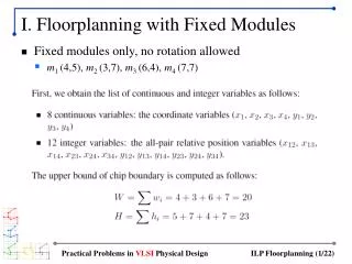
How Do I Control These Modules? • These devices get their operating instructions through a set of registers • The CPU can modify these registers through memory addresses • “Memory-Mapped Registers” • What do these registers do? • Where do I find them? • The Controller’s Users Manual is the definitive source!
Internal Memory Map (MPC555 user’s manual, Appendix A)
A Simple MMR-Driven Device Periodic Interrupt Timer • This basic timer has many uses • To implement a clock • To check user input periodically • To monitor environment changes • To switch between programs
Periodic Interrupt Timer A timer is basically a counter of clock cycles.
Periodic Interrupt Timer Time Period = (count + 1) × clock cycle time = (count + 1) / clock frequency EX: The clock frequency is 5MHz. The needed time period is 10ms. What is the count value?
Periodic Interrupt Timer Time Period = (count + 1) × clock cycle time = (count + 1) / clock frequency EX 2: The clock frequency is 5MHz. The needed time period is 1 sec. What is the count value? FYI: The count register is 16-bit
Periodic Interrupt Timer • How to program a timer? • Set up count value • Check if the timer expires • Configure interrupt, if interrupt is to be used • Read current value (if supported)
What does the manual say? • Check the table of contents: (Page 6-15 has a short description of what the timer does)
MPC555 PIT Programming 3 Registers form the MPC555 PIT programming interface • PICSR: Periodic Interrupt Control & Select Register • PITC: PIT Counter • PITR: Periodic Interrupt Timer Register
MPC555 PIT Programming PICSR: Periodic Interrupt Control & Select Register 0x002FC240 PInterrupt Enable 0: disable interrupt 1: enable interrupt Interrupt levelfor PIT 1 2 3 4 5 6 7 0 PIRQ PS PIE PITF PTE 9 10 11 12 13 14 15 8 PITFreeze 0: no effect 1: disable decrement counter if internal signal FREEZE is asserted PITEnable 0: enable decrement counter 1: disable decrement counter PIT Status 0: no PIT int asserted 1: PIT int asserted
MPC555 PIT Programming PTE: PIT enable PIF: PIT freeze PITC: PIT count value PS: PIT status PIE: PIT interrupt enable PITR: current counter value (Read-Only)
0 16 PITC PITC: PIT counter PITC: PIT Counter 0x2F C244 PIT Time-out period = (PITC+1)/(PIT Frequency) PIT Frequency depends on another module…
PITR: Periodic Interrupt Timer Register If you want to read the current PIT count to estimate time to next PIT interrupt? 0x2F C248 0 15 16 31 PIT Reserved PIT: Leftover (current) count in PIT counter Writes to PITR have no effect: read only.
PIT Initialization ; r4 base address of SIU regs lis r4, 0x2f ; set PISCR bits: PIRQ=08, PS=PS, PIE=1, PITF=0, PTE=0 ; so flag is cleared, interrupt is enabled, timer is ; enabled, and level is assigned (Level 0) li r0,0x0804 sth r0,0xC240(r4) ;PITC = 33000 = 0x80e8 and store it in PITC (0x2fc244) li r5, 0x80e8 sth r5, 0xC244(r4) ;now enable PIT: PTE = 1 lhz r0, 0xC240(r4) ori r0, r0, 0x1 sth r0, 0xC240(r4)
How to handle a PIT Interrupt Easy, as far as module handlers go Write a ‘1’ to the PS field. This indicates that you’ve handled the interrupt, and the count will immediately start over again with the same period (from PITC) If you want to change the period, modify PITC.
Software Watchdog Timer • Timer used to guarantee forward progress for the processor. • SWT must get attention every so often, or it will generate a NMI (reset)