Metal Forming and Theory of Plasticity: Open Die Forging Processes
220 likes | 412 Vues
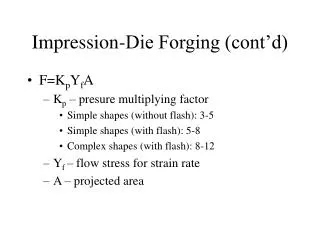
Learn about the direct compression in plane strain and open die forging processes. Understand force balance in a slab and the von-Mises criterion. Examples and solutions provided for practical understanding.

Metal Forming and Theory of Plasticity: Open Die Forging Processes
E N D
Presentation Transcript
ME 612 Metal Forming and Theory of Plasticity 15. OpenDieForgingProcesses Assoc.Prof.Dr. Ahmet Zafer Şenalpe-mail: azsenalp@gmail.com Mechanical Engineering Department Gebze Technical University
15.1. DirectCompression in PlaneStrain 15. OpenDieForgingProcesses Figure 15.1. Force balance in a slab. Mechanical Engineering Department, GTU
15.1. DirectCompression in PlaneStrain 15. OpenDieForgingProcesses Let us consider the workpiece at a given height h. Lets assume that the average yield stress of the material at this stage is Y. Take ,, as the principal stresses. The expression for is the result of the plane strain conditions and p is the pressure at the die/workpiece interface. Assume little effect of friction on principal stresses. For plane strain conditions, the von-Mises criterion becomes: The force equilibrium equation for the slab in the x direction is the following: or after simplification (15.1) (15.2) (15.3) Mechanical Engineering Department, GTU
15.1. DirectCompression in PlaneStrain 15. OpenDieForgingProcesses But from equation (15.1) dσx = -dp (note that Y is constant for a given h ). Substitution of the above equation in equation (15.3) results in the following: We need some boundary conditions to integrate the above equation: At we know that (free surface). Using the von-Mises criterion at the free surface results in the following: Using equation (15.5) and integrating equation (15.4) from position x to position b/2 results in the following: (15.4) (15.5) (15.6) Mechanical Engineering Department, GTU
15.1. DirectCompression in PlaneStrain 15. OpenDieForgingProcesses The maximum value for p occurs at the centerline where Also of great interest ispavgi.e. the average or mean pressure at the tool-workpiece interface (for a given height h) For simplicity, let a=b/2 and c=μ/h in the following derivation: (15.7) (15.8) (15.9) (15.10) Mechanical Engineering Department, GTU
15.1. DirectCompression in PlaneStrain 15. OpenDieForgingProcesses (15.11) (for small ) (15.12) Figure 15.2. Illustration of the friction hill in plane strain compression for different values of the friction coefficient. Mechanical Engineering Department, GTU
15.1. DirectCompression in PlaneStrain 15. OpenDieForgingProcesses Recall thatis the yield stress in shear for the von-Mises criterion. The earlier results for the pressure, maximum pressure and average pressure can now be written in terms of k as follows: From equation (15.13) it is obvious (see also Fig. 15.2) (15.13) (15.14) (15.15) (for small ) (15.16) Mechanical Engineering Department, GTU
15.1. DirectCompression in PlaneStrain 15. OpenDieForgingProcesses Example1: Plane-strain compression is conducted on a slab of metal whose yield shear strength; k=15000 psi dır. The width of the slab is 8 inches while its height is 1 inch. Assuming the average coefficientof friction at each interface is 0.10, • Estimate the maximum pressure at the onset of plastic flow, and • Estimate the average pressure at the onset of plastic flow. Solution: 1. 2. First, use the exact solution: (15.17) psi psi (15.18) Mechanical Engineering Department, GTU
15.2. Sticking Friction Approximation for Plane Strain Forging 15. OpenDieForgingProcesses As just indicated, there is a limit at which sliding friction can exist at the tool-workpiece interface:if that is reached, then interfacial shear of the workpiece occurs and the frictional forces indicated as p are replaced by the yield shear stress k. Following the previous analysis the result assumingsticking friction in the whole workpiece/die interface is given as (see Figure 15.4 for a slab analysis pictorial): Figure 15.3 Force balance in a slab for the sticking friction approximation (plane strain). Mechanical Engineering Department, GTU
15.2. Sticking Friction Approximation for Plane Strain Forging 15. OpenDieForgingProcesses which predicts a linear variation ofp from the outer edge to the centerline. The maximum value,which occurs at the centerline, is The average pressure is given as follows: Figure 15.4 shows the friction hill for plane-strain compression with sticking friction. (15.19) (15.20) (15.21) Figure 15.4. Friction hill in plane-strain compression for sticking-friction. Mechanical Engineering Department, GTU
15.2. Sticking Friction Approximation for Plane Strain Forging 15. OpenDieForgingProcesses Example 2: Repeat previous example assuming sticking friction at each interface. Solution: 1. 2. Note: When lubrication is used between the tools and the workpiece, 0<m<1 In this case, psi psi Mechanical Engineering Department, GTU
15.3. AxisymmetricCompression 15. OpenDieForgingProcesses For a constant value of μ, a force balance in the radial direction gives or: (if higher order terms are neglected.) With axisymmetric flow, , so , and for yielding or . Inserting these into equation (15.22) gives or (15.22) (15.23) (15.24) (15.25) Mechanical Engineering Department, GTU
15.3. AxisymmetricCompression 15. OpenDieForgingProcesses Figure 15.5. Slab for radial force balance in axisymmetric forging. Mechanical Engineering Department, GTU
15.3. AxisymmetricCompression 15. OpenDieForgingProcesses Since when r=R we have that: p=Y when r=R. Integration of the above equation r to R gives the following: The average pressure is defined as follows: from which we calculate that: or using a Taylor series expansion to approximate the exponential term in the equation above : The equation above is a good approximation to pavg for small values of and moderate values of R/h. (15.26) (15.27) (15.28) (15.29) Mechanical Engineering Department, GTU
15.4. PressureDistributionUnder StickingFrictionConditions 15. OpenDieForgingProcesses Figure 15.6. Slab for radial force balance in axisymmetric forging with sticking friction. Mechanical Engineering Department, GTU
15.4. PressureDistributionUnder StickingFrictionConditions 15. OpenDieForgingProcesses If sticking friction occurs, you can easily show that: Force balance in the rdirection: 2kdr=-hdp Pressure distribution: Average pressure: Note in the last 3 formulas, the term Y mes from the von-Mises yield condition, whereas the term k results from the sticking friction shear stress. Of course, do not forget that for the von Mises criterion, Mechanical Engineering Department, GTU
15.4. PressureDistributionUnder StickingFrictionConditions 15. OpenDieForgingProcesses Example 3: A solid disc of 4 inch diameter and 1 inch height is to be compressed. If the tensile and shear yield stresses for this metal are 50,000 and 25,000 psi respectively, estimate the force needed to start plastic flow. Solution: The average pressure at the start of flow is found: Then psi lbf Mechanical Engineering Department, GTU
15.4. PressureDistributionUnder StickingFrictionConditions 15. OpenDieForgingProcesses Barreling: A workpiece under an open-die forging process develops a barrel shape. This is caused primarily by frictional forces that oppose the outward flow of the material at the contact interfaces. Barreling also occurs in upsetting hot workpieces between cold dies. The material at and near the interfaces cools rapidly, while the rest of the specimen is relatively hot. Because the strength of the material decreases with temperature, the ends of the specimen show greater resistance to deformation than does the center. Thus the central portion of the cylinder deforms to a greater extent than do its ends. Mechanical Engineering Department, GTU
15.5. How Do You Handle The Above Calculations For A Hardening Material:() 15. OpenDieForgingProcesses For simplicity let us also discuss the plane strain compression of a block. Let us consider the block at an intermediate height h Note that due to incompressibility i.e. B is uniquely determined given h. From the plane strain conditions we can write the effective strain as: The (current) yield stress of the workpiece of height h is given then as follows: . Notice how the yield stress varies with h. You can now use this value of Y in any of the formulas given above for the pressure. Don’t forget that the method described for hardening case is an approach and includes error. Mechanical Engineering Department, GTU