Future of Power Generation: Sustainable Solutions for National Energy Needs
This course delves into the challenges and solutions in power generation, covering renewable energy sources like wind and solar power. It explores different vapor power plant configurations, emphasizing the importance of thermodynamic cycles. Understanding the mechanisms of vaporization in various plant types, such as fossil-fueled, nuclear, solar, and geothermal, is crucial in meeting growing energy demands sustainably. The course delves into the Rankine cycle, thermal efficiencies, and the optimization of power cycles. Explore the vital role of piston-cylinder systems in energy applications for transportation and beyond.

Future of Power Generation: Sustainable Solutions for National Energy Needs
E N D
Presentation Transcript
ME 200 L13: Energy Applications: Stationary; Energy Applications: Transportation Spring 2014 MWF 1030-1120 AMJ. P. Gore gore@purdue.eduGatewood Wing 3166, 765 494 0061Office Hours: MWF 1130-1230TAs: Robert Kapaku rkapaku@purdue.edu Dong Han han193@purdue.edu
Introducing Power Generation • To meet our national power needs there are challenges related to • Declining economically recoverable supplies of nonrenewableenergy resources. • Effects of global climate change and other environmental and human health and safety issues. • Rapidly increasing demand for power owing to increasing population. • Today we are heavily dependent on coal, natural gas, and nuclear, all of which are nonrenewable.
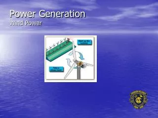
Introducing Power Generation • While coal, natural gas, and nuclear will continue to play important roles in years ahead, contributions from wind power, solar power, and other renewable sources are expected to be increasingly significant up to mid-century at least. Table 8.2
Introducing Power Generation • Table 8.2 also shows that thermodynamic cycles are a fundamental aspect of several power plant types that employ renewable or nonrenewable sources. • In Chapters 8 and 9, vapor power systems, gas turbine power systems, and internal combustion engines are studied as thermodynamic cycles. Vapor power systems in which a working fluid is alternately vaporized and condensed is the focus of Chapter 8. The basic building block of vapor power systems is the Rankine cycle.
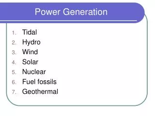
Introducing Vapor Power Plants • The components of four alternative vapor power plant configurations are shown schematically in Fig. 8.1. They are • Fossil-fueled vapor power plants. • Pressurized-water reactor nuclear vapor power plants. • Concentrating solar thermal vapor power plants. • Geothermal vapor power plants. • In each of the four types of vapor power plant, a working fluid is alternately vaporized and condensed. A key difference among the plants is the origin of the energy required to vaporize the working fluid.
Introducing Vapor Power Plants • In fossil-fueled plants, the energy required for vaporization originates in combustion of the fuel.
Introducing Vapor Power Plants • In nuclear plants, the energy required for vaporization originates in a controlled nuclear reaction.
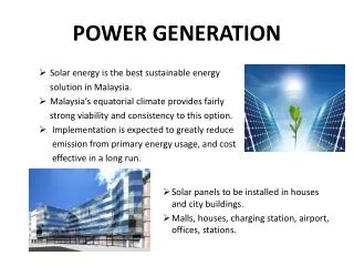
Introducing Vapor Power Plants • In solar plants, the energy required for vaporization originates in collected and concentrated solar radiation.
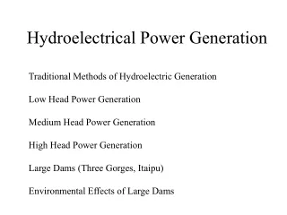
Introducing Vapor Power Plants • In geothermal plants, the energy required for vaporization originates in hot water and/or steam drawn from below the earth’s surface.
Introducing Vapor Power Plants • The fossil-fueled vapor power plant of Fig. 8.1(a) will be considered as representative. The overall plant is broken into four major subsystems identified by A, B, C, and D. Water is the working fluid.
Introducing Vapor Power Plants • Subsystem A provides the heat transferof energy needed to vaporize water circulating in subsystem B. In fossil-fueled plants this heat transfer has its origin in the combustion of the fuel.
Introducing Vapor Power Plants • In subsystem B,thewater vapor expands through the turbine, developing power. The water then condenses and returns to the boiler.
Introducing Vapor Power Plants • In subsystem C,power developed by the turbine drives an electric generator.
Introducing Vapor Power Plants • Subsystem D removes energy by heat transfer arising from steam condensing in subsystem B.
Introducing Vapor Power Plants • Each unit of mass of water periodically undergoes a thermodynamic cycle as it circulates through the components of subsystem B. This cycle is the Rankine cycle.
∙ ∙ ∙ Wcycle = Qin – Qout Power Cycle Review • The first law of thermodynamics requires the net work developed by a system undergoing a power cycle to equal the net energy added by heat transfer to the system: ∙ ∙ • The thermal efficiency of a power cycle is ∙
Power Cycle Review • The second law of thermodynamics requires the thermal efficiency to be less than 100%. Most of today’s vapor power plants have thermal efficiencies ranging up to about 40%. • Thermal efficiency tends to increase as the average temperature at which energy is added by heat transfer increases and/or the average temperature at which energy is rejected by heat transfer decreases. • Improved thermodynamic performance of power cycles, as measured by increased thermal efficiency, for example, also accompanies the reduction of irreversibilities and losses. • The extent of improved power cycle performance is limited, however, by constraints imposed by thermodynamicsandeconomics.
Energy Application: TransportationPiston Cylinder Systems • Piston cylinder systems are widely used • There function is to transfer expansion and compression energy change into linear motion and eventually rotary motion. Applications: I. C. engines, hydraulic jacks, bicycle air-pump, balloon inflator etc. Stroke=Crank circle diameter. The cylinder length must clear the end to end motion of the connecting rod. The clearance volume defines the compression ratio. The BDC volume defines the cylinder capacity. The pressure, temperature and volume within the cylinder are related and determine power output.