RADIOGRAPHIC TESTING
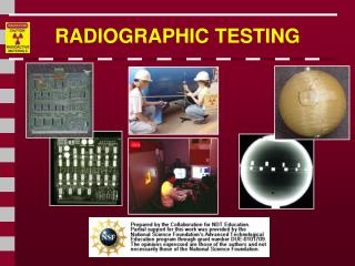
RADIOGRAPHIC TESTING. Introduction. This module presents information on the NDT method of radiographic inspection or radiography. Radiography uses penetrating radiation that is directed towards a component.

RADIOGRAPHIC TESTING
E N D
Presentation Transcript
Introduction • This module presents information on the NDT method of radiographic inspection or radiography. • Radiography uses penetrating radiation that is directed towards a component. • The component stops some of the radiation. The amount that is stopped or absorbed is affected by material density and thickness differences. • These differences in “absorption” can be recorded on film, or electronically.
Outline • Electromagnetic Radiation • General Principles of Radiography • Sources of Radiation • Gamma Radiography • X-ray Radiography • Imaging Modalities • Film Radiography • Computed Radiography • Real-Time Radiography • Direct Digital Radiography • Computed Radiography • Radiation Safety • Advantages and Limitations • Glossary of Terms
Electromagnetic Radiation The radiation used in Radiography testing is a higher energy (shorter wavelength) version of the electromagnetic waves that we see every day. Visible light is in the same family as x-rays and gamma rays.
The part is placed between the radiation source and a piece of film. The part will stop some of the radiation. Thicker and more dense area will stop more of the radiation. = less exposure = more exposure General Principles of Radiography The film darkness (density) will vary with the amount of radiation reaching the film through the test object. X-ray film Top view of developed film
General Principles of Radiography • The energy of the radiation affects its penetrating power. Higher energy radiation can penetrate thicker and more dense materials. • The radiation energy and/or exposure time must be controlled to properly image the region of interest. Thin Walled Area Low Energy Radiation High energy Radiation
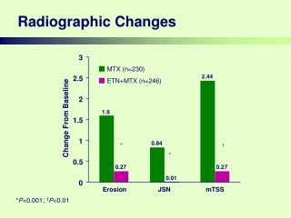
IDL 2001 Flaw Orientation Optimum Angle = easy to detect Radiography has sensitivity limitations when detecting cracks. = not easy to detect X-rays “see” a crack as a thickness variation and the larger the variation, the easier the crack is to detect. When the path of the x-rays is not parallel to a crack, the thickness variation is less and the crack may not be visible.
IDL 2001 0o 10o 20o Flaw Orientation (cont.) Since the angle between the radiation beam and a crack or other linear defect is so critical, the orientation of defect must be well known if radiography is going to be used to perform the inspection.
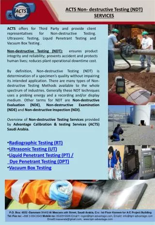
Radiation Sources Two of the most commonly used sources of radiation in industrial radiography are x-ray generators and gamma ray sources. Industrial radiography is often subdivided into “X-ray Radiography” or “Gamma Radiography”, depending on the source of radiation used.
Gamma Radiography • Gamma rays are produced by a radioisotope. • A radioisotope has an unstable nuclei that does not have enough binding energy to hold the nucleus together. • The spontaneous breakdown of an atomic nucleus resulting in the release of energy and matter is known as radioactive decay.
Gamma Radiography (cont.) • Most of the radioactive material used in industrial radiography is artificially produced. • This is done by subjecting stable material to a source of neutrons in a special nuclear reactor. • This process is called activation.
Gamma Radiography (cont.) Unlike X-rays, which are produced by a machine, gamma rays cannot be turned off. Radioisotopes used for gamma radiography are encapsulated to prevent leakage of the material. The radioactive “capsule” is attached to a cable to form what is often called a “pigtail.” The pigtail has a special connector at the other end that attaches to a drive cable.
Gamma Radiography (cont.) A device called a “camera” is used to store, transport and expose the pigtail containing the radioactive material. The camera contains shielding material which reduces the radiographer’s exposure to radiation during use.
Gamma Radiography (cont.) A hose-like device called a guide tube is connected to a threaded hole called an “exit port” in the camera. The radioactive material will leave and return to the camera through this opening when performing an exposure!
Gamma Radiography (cont.) A “drive cable” is connected to the other end of the camera. This cable, controlled by the radiographer, is used to force the radioactive material out into the guide tube where the gamma rays will pass through the specimen and expose the recording device.
X-ray Radiography Unlike gamma rays, x-rays are produced by an X-ray generator system. These systems typically include an X-ray tube head, a high voltage generator, and a control console.
X-ray Radiography (cont.) • X-rays are produced by establishing a very high voltage between two electrodes, called the anode and cathode. • To prevent arcing, the anode and cathode are located inside a vacuum tube, which is protected by a metal housing.
High Electrical Potential Electrons + - X-ray Generator or Radioactive Source Creates Radiation Radiation Penetrate the Sample Exposure Recording Device X-ray Radiography (cont.) • The cathode contains a small filament much the same as in a light bulb. • Current is passed through the filament which heats it. The heat causes electrons to be stripped off. • The high voltage causes these “free” electrons to be pulled toward a target material (usually made of tungsten) located in the anode. • The electrons impact against the target. This impact causes an energy exchange which causes x-rays to be created.
Imaging Modalities Several different imaging methods are available to display the final image in industrial radiography: • Film Radiography • Real Time Radiography • Computed Tomography (CT) • Digital Radiography (DR) • Computed Radiography (CR)
Film Radiography • One of the most widely used and oldest imaging mediums in industrial radiography is radiographic film. • Film contains microscopic material called silver bromide. • Once exposed to radiation and developed in a darkroom, silver bromide turns to black metallic silver which forms the image.
Film Radiography (cont.) • Film must be protected from visible light. Light, just like x-rays and gamma rays, can expose film. Film is loaded in a “light proof” cassette in a darkroom. • This cassette is then placed on the specimen opposite the source of radiation. Film is often placed between screens to intensify radiation.
Film Radiography (cont.) • In order for the image to be viewed, the film must be “developed” in a darkroom. The process is very similar to photographic film development. • Film processing can either be performed manually in open tanks or in an automatic processor.
Film Radiography (cont.) Once developed, the film is typically referred to as a “radiograph.”
Digital Radiography • One of the newest forms of radiographic imaging is “Digital Radiography”. • Requiring no film, digital radiographic images are captured using either special phosphor screens or flat panels containing micro-electronic sensors. • No darkrooms are needed to process film, and captured images can be digitally enhanced for increased detail. • Images are also easily archived (stored) when in digital form.
Digital Radiography (cont.) There are a number of forms of digital radiographic imaging including: • Computed Radiography (CR) • Real-time Radiography (RTR) • Direct Radiographic Imaging (DR) • Computed Tomography
Computed Radiography Computed Radiography (CR) is a digital imaging process that uses a special imaging plate which employs storage phosphors.
X-Rays Protective Layer Phosphor Layer Phosphor Grains Substrate Computed Radiography (cont.) X-rays penetrating the specimen stimulate the phosphors. The stimulated phosphors remain in an excited state. CR Phosphor Screen Structure
Computed Radiography (cont.) After exposure: The imaging plate is read electronically and erased for re-use in a special scanner system.
Computed Radiography (cont.) As a laser scans the imaging plate, light is emitted where X-rays stimulated the phosphor during exposure. The light is then converted to a digital value. Optical Scanner Photo-multiplier Tube Laser Beam A/D Converter Imaging Plate 110010010010110 Motor
Computed Radiography (cont.) Digital images are typically sent to a computer workstation where specialized software allows manipulation and enhancement.
Computed Radiography (cont.) Examples of computed radiographs:
Real-Time Radiography • Real-Time Radiography (RTR) is a term used to describe a form of radiography that allows electronic images to be captured and viewed in real time. • Because image acquisition is almost instantaneous, X-ray images can be viewed as the part is moved and rotated. • Manipulating the part can be advantageous for several reasons: • It may be possible to image the entire component with one exposure. • Viewing the internal structure of the part from different angular prospectives can provide additional data for analysis. • Time of inspection can often be reduced.
Real-Time Radiography (cont.) • The equipment needed for an RTR includes: • X-ray tube • Image intensifier or other real-time detector • Camera • Computer with frame grabber board and software • Monitor • Sample positioning system (optional)
Real-Time Radiography (cont.) • The image intensifier is a device that converts the radiation that passes through the specimen into light. • It uses materials that fluoresce when struck by radiation. • The more radiation that reaches the input screen, the more light that is given off. • The image is very faint on the input screen so it is intensified onto a small screen inside the intensifier where the image is viewed with a camera.
Real-Time Radiography (cont.) • A monitor is then connected to the camera to provide a viewable image. • If a sample positioning system is employed, the part can be moved around and rotated to image different internal features of the part. • A special camera which captures the light output of the screen is located near the image intensifying screen. • The camera is very sensitive to a variety of different light intensities.
Real-Time Radiography (cont.) Comparing Film and Real-Time Radiography Real-time images are lighter in areas where more X-ray photons reach and excite the fluorescent screen. Film images are darker in areas where more X-ray photons reach and ionize the silver molecules in the film.
Direct Radiography • Direct radiography (DR) is a form of real-time radiography that uses a special flat panel detector. • The panel works by converting penetrating radiation passing through the test specimen into minute electrical charges. • The panel contains many micro-electronic capacitors. The capacitors form an electrical charge pattern image of the specimen. • Each capacitor’s charge is converted into a pixel which forms the digital image.
Computed Tomography Computed Tomography (CT) uses a real-time inspection system employing a sample positioning system and special software.
Computed Tomography (cont.) • Many separate images are saved (grabbed) and complied into 2-dimensional sections as the sample is rotated. • 2-D images are them combined into 3-dimensional images. Real-TimeCaptures Compiled 2-DImages Compiled 3-D Structure
Image Quality • Image quality is critical for accurate assessment of a test specimen’s integrity. • Various tools called Image Quality Indicators (IQIs) are used for this purpose. • There are many different designs of IQIs. Some contain artificial holes of varying size drilled in metal plaques while others are manufactured from wires of differing diameters mounted next to one another.
Image Quality (cont.) • IQIs are typically placed on or next to a test specimen. • Quality typically being determined based on the smallest hole or wire diameter that is reproduced on the image.
Radiation Safety Use of radiation sources in industrial radiography is heavily regulated by state and federal organizations due to potential public and personal risks.
Radiation Safety (cont.) There are many sources of radiation. In general, a person receives roughly 100 mrem/year from natural sources and roughly 100 mrem/year from manmade sources.
Radiation Safety (cont.) X-rays and gamma rays are forms of ionizing radiation, which means that they have the ability to form ions in the material that is penetrated. All living organisms are sensitive to the effects of ionizing radiation (radiation burns, x-ray food pasteurization, etc.) X-rays and gamma rays have enough energy to liberate electrons from atoms and damage the molecular structure of cells. This can cause radiation burns or cancer.
Radiation Safety (cont.) Technicians who work with radiation must wear monitoring devices that keep track of their total absorption, and alert them when they are in a high radiation area. Radiation Alarm Radiation Badge Survey Meter Pocket Dosimeter
Radiation Safety (cont.) There are three means of protection to help reduce exposure to radiation:
Radiographic Images Can you determine what object was radiographed in this and the next three slides?