Enhanced Beam Injection and Transfer Line Studies for LHC: Outcomes and Future Directions
200 likes | 349 Vues
This document summarizes key findings from the 2009 optics studies and beam time measurements for the Large Hadron Collider (LHC) transfer lines. It highlights essential data on trajectory, kick response, and dispersion measurements, as well as improvements in dispersion metrics and aperture studies. The document also outlines injection region setups, steering adjustments, and performance metrics for various components. Findings confirm robust model agreements, with recommendations for additional measurements and adjustments for optimal beam performance in future LHC operations.

Enhanced Beam Injection and Transfer Line Studies for LHC: Outcomes and Future Directions
E N D
Presentation Transcript
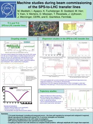
LHC Injection and transfer lines Malika Meddahi, Brennan Goddard, Verena Kain, Jörg Wenninger On behalf of all contributors In particular: K.Fuchsberger, S.Fartoukh, V.Mertens, J.Uythoven, M.Barnes, E. Carlier, W.Bartmann, C.Hessler, L.Jensen, R.Jones, M.Lamont, R.Giachino, G.Mueller, S.Redaelli, W.Herr, F.Schmidt, OP crews on shift…
Scope • LHC transfer lines – 2009 optics studies • Trajectory • Dispersion • Kick response • Aperture • Injection regions • Injection steering • MKI wave form • Injection protection • Injection aperture • List of subjects to follow-up
1- LHC Transfer line Main outcomes from all transfer line beam time measurements – trajectory, kick response and dispersion measurements: • Transfer line BPMs: • calibration performed and included in the measurements -Rhodri, Lars and team • + essential data from kick response measurements (Kajetan) • request for additional BPMs upstream of TT60 – hidden trajectory bump – • available for 2011 start-up • more robust dispersion measurements in TI 8 thanks to the dual plane reading • and the additional BPMs in the LHC injection area • in TI 2, same improvements will be available for the 2011 start-up– BI teams
Trajectory examples TI 8 bare trajectory TI 8 corrected trajectory -few correctors, <20 mrad
Transfer line magnetic model: • TT60 MBE CC switched to MBB – vertical bare trajectory as expected • MQIs DK/K = ~1.006 • MQI measurements by magnet group • MBI sext. component of ~ -4.5e-4 @ r=25mm (idea from S.Fartoukh) • Confirmed by magnet group from 2D calculations • MBI quad. component of ~1.35e-4 @ r=25mm • Feed-down from systematic horizontal offset in MBI Nominal Idem + Dk/k+b2+b3 Idem + initial cdts Rematched optics with b2,b3 components and use new MQI CC
Kick response measurements – TI 8 - V plane – Before rematching ~ 0.7% over-focussing in vertical plane apparent cf model Courtesy: Kajetan Kick response measurements – TI 8 - V plane – After rematching
Dx TI 8 1st and 2nd order dispersion with rematched optics D’x
TI 2 and TI 8 aperture studies • - Momentum aperture: +/- 0.35 to 0.4%, as expected. • - Physical aperture explored in both lines in H and V, at different phases, 30 deg intervals, using on-line model and dedicated knobs
In both planes in both lines: • No bottlenecks • Note: aperture restriction between • P8 MSI and Q5 solved after • re-alignments - Measured aperture ≥10 nominal s Few phases in TI 2 to complete
2- Injection region Much injection checks and setting-up work performed through the LHC beam commissioning • Injection steering • Injection region aperture • Kick response – dispersion measurements • MKI waveform • TDI and TCLIA/B setting up around orbit, LHCb BeamCdtMonitor, setup of TDIs to golden orbit – see Wolfgang’s talk • Checked losses on TDI & IR8 for MKI off/over-injecting – see Christos’ talk • Tests of injection and matching with xing/sep bumps on – see Werner’s talk • Injection kicker timing in • Injection of multiple bunches • …
TI 2-TI 8 Steering • TI 2+S23 and TI 8+S78 selections of the steering display now by default: • TL trajectory • Ring First turn - Closed orbit = injection oscillation • Closed orbit is estimated from average of 50 first turns • >> ensures that TL steering always brings beam onto the CO Trajectory FT-CO 11
Injection Autopilot • Feedback tools inside steering program to correct injection oscillations: • Same tool used for SPS injection oscillations & SPS target steering. • Manually activated. • Algorithm can be configured (DB). Presently: • Fit a betatron oscillation to the ring FT-CO • (in H subtract dp/p error). • Interpolate fit to a virtual start point (pos + angle). • If pos/angle out of tolerance, correct • with 2 correctors at end of line. • >> tested & works well ! • May need to tune algorithm because of TL collimation. • Global MICADO (towards ref) better? • >> need more experience ! 12
Kick response measurements -1 Data in very good agreement with model. All measurements were done at deltap/p = - 0.5 permil. Figures show a comparison between measurements (blue) and model (red). Beam from left. H plane V plane Courtesy Kajetan
Kick response measurements -2 H+V response of horizontal kicker MCIAH.80204 for TI8 and LHC sector 78. H+V response for vertical kicker MCIAV.80704 for TI8 and LHC sector 78. Vertical (blue background) couples to horizontal (red background) Courtesy Kajetan
Point 2 / 8 TDI and TCLIA/B setting up • Transfer line protection devices: setting up partially done • TDI / TCDI : done • See Wolfgang Bartmann presentation
MKI 2 and 8 waveform measured Looks OK except for 2% overshoot, both MKI2 and 8 – being corrected Courtesy M.Barnes
Injection kicker timing in • Both beams timed in • Adjusted with OASIS signals • Configured for abort gap keeper • Checked beam injected OK with acceptable oscillations • Need to check the fine timing to fit full SPS batch Beam2 Beam1
Multiple bunch injection (and fixes) • 4 bunch injection sequences worked after timing in MKI and MKD • Need to be aware that injecting near to abort gap needs consideration • bunch is always at the head of the injection kicker pulse – always 11 ms gap as result after last bunch • may need to reorder some injection sequences, especially with ‘trailing pilot’ • may need to change order of injection for some bunches. • Setting up of protection devices to (re)do for high intensity
3- List of subjects to follow-up • Transfer lines: Importance of: • Regular survey checks and re-alignment • Steering with minimum corrector number and strength • Accurate characterisation of the main magnets • Noise on QPS from TF pulsing? Worry about other EMC sources around ring? • Injection region: • FT-CO evaluation is presently based on FIFO acquisition: • Works only when injecting into EMPTY ring. • To be able to work on ANY injection (also with circ. beam): • FT-CO from capture data. Code written – needs testing. • Capture data must be automatically configured and enabled to trigger on the buckets corresponding to the injected bunches (>> injection sequencer). • ‘Interference’ with PC interlocks of TLs: • Corrector interlock margin presently +- 10 mrad (from CNGS experience). • Must find a compromise between protection (small tol.) and steering flexibility (larger tol.). Note that shift crews have the right to change the corrector reference settings (not the tolerance).
Injection region (cont’d): • Still investigate how to over-inject without interlocking • Puzzle of losses in P8 on MQX – issue of BLM range • Fine synchronisation of injection kicker pulse to bucket 1 • Setting up of TCDIs and TCLIA/Bs • Losses on TCDQ/TCSG for B1 at injection– (more) checks to make • BQM information for IQC – to be made operational • Injection sequences to revisit with ‘trailing pilot’ • May need to change order of injection for some bunches. • Need adequate (re)commissioning time