Fire protection systems
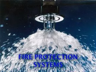
Fire protection systems. Fire Sprinkler Systems. Fire Lines. Components Water main DCVA – Double Check Valve Assembly Fire Department Connection (FDC) Indicator Valve Assembly Post Indicator Valve (PIV) Wall Post Indicator Valve (WPIV). DCVA. Control Valve. Check Valve.

Fire protection systems
E N D
Presentation Transcript
Fire Lines Components • Water main • DCVA – Double Check Valve Assembly • Fire Department Connection (FDC) • Indicator Valve Assembly • Post Indicator Valve (PIV) • Wall Post Indicator Valve (WPIV)
DCVA Control Valve Check Valve
City of Bothell Requirements • Locations of FDCs • Within 50 feet of structure. • Within 50 feet of a fire hydrant. (Outside of the Downtown Sub area) • Can be combination or single use. • Painted • Labeled for type and address (If needed) As the downtown sub-area becomes more densely developed, you will see more wall mounted connection and control points.
Indicator Valve Assemblies Post Indicator Valve. Wall Post Indicator Valve. • Outside Screw and yoke • Purpose: • To control the flow of water to the fire protection system. • Visible indicator of the position of the device. • OPEN/SHUT • Visible screw threads • Security • Chains • Tamper device
General Design Standard for the City of Bothell FDC Check Valve Feed from main PIV Control Valve Fire Line
Fire Suppression Riser • Purpose • To control and distribute the water to the suppression devices. • To allow reporting to a notification device of tampering or water flow. • Risers come in many forms, from a standard wet pipe riser to much more complicated systems.
Shot Gun Riser • Water is in the system at all times. • Released by the activation of a sprinkler head.
Dry Pipe Riser • Used for areas subject to freeze. • The piping above the valve assembly has no water in it. • Usually has an air compressor to hold back the water from entering the pipes in non-alarm conditions.
Dry Pipe Riser Pressurized Air Face Bolt Latch Dry area of riser Valve Cap Hinge Water Inlet
Basic Principle • Heat from combustion breaks the bulb or fusible link on a sprinkler head. • Pressurized air in the branch and main lines travels through the system escaping through the opened sprinkler head or heads. • Air from the system leaves the main chamber of the riser valve. • Release of the pressurized air allows for the valve to lift off the inlet. • Water moves from the main line into the system lines.
Special Requirements • Time constraints for air to leave the system and water to reach the sprinkler head. • NFPA 13 – 60 seconds of less for water delivery. • If the system takes too long… • An “Accelerator” may be needed. • Air compressor to keep pressure in the system and keep the main alarm valve from opening. • Signal to alarm system when system goes “WET”.
Pre-Action System • Usually used for areas within a building that may need special application due to sensitive equipment or where accidental activation is undesired. • Pre-action systems are hybrids of wet, dry, and deluge systems, depending on the exact system goal. • There are two main sub-types of pre-action systems: single interlock, and double interlock.
Pre-Action • Single interlock systems are similar to dry systems except that these systems require that a “preceding” fire detection event, typically the activation of a heat or smoke detector, takes place prior to the “action” of water introduction into the system’s piping by opening the pre-action valve, which is a mechanically latched valve.
Pre-Action • Double interlock systems are similar to deluge systems except that automatic sprinklers are used. • These systems require that both a “preceding” fire detection event, typically the activation of a heat or smoke detector, and an automatic sprinkler operation take place prior to the “action” of water introduction into the system’s piping.
Pre-Action • Activation of either the fire detectors alone, or sprinklers alone, without the concurrent operation of the other, will not allow water to leave the piping system. • Because water does not enter the piping until a sprinkler operates, double interlock systems are considered as dry systems in terms of water delivery times, and similarly require a larger design area.
Deluge System • In these systems, sprinklers are open at all times. • There is NO fusible link or temperature sensitive bulb.
Deluge System • A fire detection device controls the main valve. • Very similar to a pre-action system. • When the system is activated, the valve opens, allowing large amounts of water to flow through all of the sprinklers. • They are usually used in facilities that contain hazardous materials such as: flammable liquids, chemicals, and explosives.
Standpipe System • A system of pipes and connection points. • Mainly used to extend the reach of hose lines. • Typical connections are 2 ½ inch and 1 ½ inch. • Connections are normally located in stairwells. • Can also be found in hallways, roofs and places where the spacing between access points exceeds 300 feet.
Standpipe System Systems can be as complicated as the building and its contents require.
Standpipe System • System can be normally dry. • Supplied by water from a fire apparatus. • System can be normally wet. • Supplied by water from the fire line. • Supplemented with water from a fire apparatus. • System can be a combination. • Combined with the sprinkler system.
Standpipe System Class I – A Class I standpipe system shall provide a 2 1/2 inch hose connection for use primarily by trained personnel or by the fire department during initial response. This class has no hose attached.
Standpipe System Class II – A Class II standpipe system shall provide 1 1/2 inch hose stations to supply water for use primarily by trained personnel or by the fire department during initial response. These are typically found in cabinets with 100’ of hose.
Standpipe System Class III – A Class III standpipe system shall provide 1 1/2 inch hose stations to supply water for use by trained personnel and a 2 1/2 inch hose connection to supply a larger volume of water for use by fire departments and those trained in heavy fire streams. Many times these connections will provide a 2-1/2 inch reducer to a 1-1/2 hose connection.
Special Extinguishing Systems • FM-200 • An extinguishing system that utilizes a chemical extinguishing agent. • The agent is less hazardous than Halon. • Leaves no residue on equipment. • Uses a interlock release system. • Usually smoke detectors. • Countdown timer to allow for escape from the room prior to release. • Manual activation and abort buttons. • Visual and audible alarms.
FM-200 System Extinguishing agent canister Discharge Nozzles
FM-200 System Temporary abort button Manual Activation button
Kitchen Hood Systems • NFPA 96 Standard for Ventilation Control and Fire Protection of Commercial Cooking Operations • NFPA 13 Standard for the Installation of Sprinkler Systems • NFPA 17 Standard for Dry Chemical Extinguishing Systems • NFPA 17A Standard for Wet Chemical Extinguishing Systems • UL 300 Standard for Fire Testing of Fire Extinguishing Systems for Protection of Commercial Cooking Equipment • UL 710 Standard for Exhaust Hoods for Commercial Cooking Equipment These are just some of them.
Kitchen Hood Systems • Why do we need hood extinguishing systems? • What are some of the hazards associated with kitchen cooking? • How frequently are hoods to be cleaned? • How frequently are the suppression components to be serviced? • What types of extinguishing agents are used?
Kitchen Hood Systems NFPA 96 Cleaning schedule • Monthly - Facilities that serve solid fuel cooking need to be cleaned. • Quarterly - Facilities that serving high volume cooking like 24hr restaurants and wok cooking . • Semi- Annual - Facilities that serve moderate volume cooking to be cleaned. • Annually - Facilities that serve low volume cooking like churches, day camps, senior centers.
Kitchen Hood Systems Typical System Layout
Kitchen Hood Systems Grease build up on roof
Kitchen Hood Systems A dirty hood system
Kitchen Hood Systems Grease baffle filters
Kitchen Hood Systems A duct with heavy build up