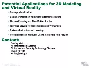
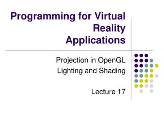
Programming for Virtual Reality Applications
Programming for Virtual Reality Applications. Projection in OpenGL Lighting and Shading Lecture 17. v e r t e x. Modelview Matrix. Projection Matrix. Perspective Division. Viewport Transform. Modelview. Projection. Modelview. l l l. Transformation Pipeline.

Programming for Virtual Reality Applications
E N D
Presentation Transcript
Programming for Virtual RealityApplications Projection in OpenGL Lighting and Shading Lecture 17
v e r t e x Modelview Matrix Projection Matrix Perspective Division Viewport Transform Modelview Projection Modelview l l l TransformationPipeline • other calculations here • material è color • shade model (flat) • polygon rendering mode • polygon culling • clipping normalized device eye object clip window
Matrix Operations • Specify Current Matrix Stack • glMatrixMode( GL_MODELVIEW or GL_PROJECTION ) • Other Matrix or Stack Operations • glLoadIdentity() • glPushMatrix() • glPopMatrix() • Viewport • usually same as window size • viewport aspect ratio should be same as projection transformation or resulting image may be distorted • glViewport( x, y, width, height )
Projection Transformation • Shape of viewing frustum • Perspective projection gluPerspective( fovy, aspect, zNear, zFar ) glFrustum(left,right,bottom,top,zNear,zFar) • Orthographic parallel projection glOrtho(left,right,bottom,top,zNear,zFar) gluOrtho2D( left, right, bottom, top ) • calls glOrtho with z values near zero
Applying Projection Transformations • Typical use (orthographic projection) glMatrixMode( GL_PROJECTION ); glLoadIdentity(); glOrtho( left, right, bottom, top, zNear, zFar );
tripod Viewing Transformations • Position the camera/eye in the scene • place the tripod down; aim camera • To “fly through” a scene • change viewing transformation andredraw scene • gluLookAt( eyex, eyey, eyez, aimx, aimy, aimz, upx, upy, upz ) • up vector determines unique orientation
Modeling Transformations • Move object glTranslate{fd}( x, y, z ) • Rotate object around arbitrary axis glRotate{fd}( angle, x, y, z ) • angle is in degrees • Dilate (stretch or shrink) or mirror object glScale{fd}( x, y, z )
Connection: Viewing and Modeling • Moving camera is equivalent to moving every object in the world towards a stationary camera • Viewing transformations are equivalent to several modeling transformations gluLookAt() has its own command can make your own polar view or pilot view
Projection is left handed • Projection transformations (gluPerspective, glOrtho) are left handed • think of zNear and zFar as distance from view point • Everything else is right handed, including the vertexes to be rendered y y z+ left handed right handed x x z+
Building geometry using coordinates • Construct a pyramid by connecting the dots to form triangles
Winding Rule • Using a right-handed coordinate system • 3D coordinates are given in a right-handed coordinate system • X = left-to-right . • Y = bottom-to-top . • Z = back-to-front . • Distances are conventionally in meters 扶
Using coordinate order • Polygons have a front and back: • By default, only the front side of a polygon is rendered . • A polygon's winding order determines which side is the front . • Most polygons only need one side rendered . • You can turn on double-sided rendering, at a performance cost .
Using coordinate order • Use the right-hand rule: • Curl your right-hand fingers around the polygon perimeter in the order vertices are given (counter-clockwise) • Your thumb sticks out the front of the polygon
Back-face elimination ... culling Two Sides to a Polygon: • Most polygonal meshes have a well-defined inside and outside. • We use the right-hand rule (CCW counterclockwise winding) and specify vertices in a counterclockwise order to indicate the outside face. Culling in OpenGL: • By default, OpenGL considers polygons with counterclockwise specification to be front facing. If we specify, or render, in the opposite direction, we are rendering the back face (inward-facing face of a solid).
We use the right-hand rule (CCW) to specify the vertices that make up the outside faces of a polygon.
Common Transformation Usage • 3 examples of resize() routine • restate projection & viewing transformations • Usually called when window resized • Registered as callback for glutReshapeFunc()
resize(): Perspective & LookAt void resize( int w, int h ) { glViewport( 0, 0, (GLsizei) w, (GLsizei) h ); glMatrixMode( GL_PROJECTION ); glLoadIdentity(); gluPerspective( 65.0, (GLdouble) w / h, 1.0, 100.0 ); glMatrixMode( GL_MODELVIEW ); glLoadIdentity(); gluLookAt( 0.0, 0.0, 5.0, 0.0, 0.0, 0.0, 0.0, 1.0, 0.0 ); }
resize(): Perspective & Translate Same effect as previous LookAt void resize( int w, int h ) { glViewport( 0, 0, (GLsizei) w, (GLsizei) h ); glMatrixMode( GL_PROJECTION ); glLoadIdentity(); gluPerspective( 65.0, (GLdouble) w/h, 1.0, 100.0 ); glMatrixMode( GL_MODELVIEW ); glLoadIdentity(); glTranslatef( 0.0, 0.0, -5.0 ); }
resize(): Ortho void resize( int width, int height ) { GLdouble aspect = (GLdouble) width / height; GLdouble left = -2.5, right = 2.5; GLdouble bottom = -2.5, top = 2.5; glViewport( 0, 0, (GLsizei) w, (GLsizei) h ); glMatrixMode( GL_PROJECTION ); glLoadIdentity(); if ( aspect < 1.0 ) { left /= aspect; right /= aspect; } else { bottom *= aspect; top *= aspect; } glOrtho( left, right, bottom, top, near, far ); glMatrixMode( GL_MODELVIEW ); glLoadIdentity(); }
Compositing Modeling Transformations • Problem 1: hierarchical objects • one position depends upon a previous position • robot arm or hand; sub-assemblies • Solution 1: moving local coordinate system • modeling transformations move coordinate system • post-multiply column-major matrices • OpenGL post-multiplies matrices
Compositing Modeling Transformations • Problem 2: objects move relative to absolute world origin • my object rotates around the wrong origin • make it spin around its center or something else • Solution 2: fixed coordinate system • modeling transformations move objects around fixed coordinate system • pre-multiply column-major matrices • OpenGL post-multiplies matrices • must reverse order of operations to achieve desired effect
Lighting, Shading • Lighting and shading give objects “shape” • Important effects • shading • shiny highlights • reflections • shadows • Local techniques simplify these effects to improve performance
Shading/ lighting • Diffuse ambient light creates no shading... Simplest • Illumination can vary by angle between N (normal to the polygon) and L (the source) • Source of illumination can be a point or a region (expressed as cosng). The larger the n the narrower the beam • Compute N and L across polygon face
Shading • Can interpolate shade across a polygon • Gouraud shading interpolates shade across edges, reduces effect of intensity change. • Phong shading (and illumination) interpolates surface normal vector across polygons then interpolates illumination.
L N 1R 1V Shading • A reflection (diffuse + specular + florescence) model describes the interaction of light with a surface, in terms of the properties of the surface and the nature of the incident light. • Surface : surface normal + material (combination ofka, kd, ks and n) • I = Iaka + Ii[kd(L•N) + ks (R•V)n]/(r+k)
Shading • Compute lighting based on angle of light on polygon surface. Surface normal
Gouraud Shading • Compute shading for each pixel by averaging shading based on distance and shading of vertices.
Gouraud • Each face has a normal. • Vertex normals are the averages of the faces surrounding them. • Note: with OpenGL, user supplies vertex normals directly.
Gouraud • Once normals of vertices of face P known, then the illumination of those points can be computed with lighting equation. • Then, when scan-converting polygon P, the pixel colour (lighting) is simply linearly interpolated from these vertex lighting values. • In example right, only 4 lighting computations done; rest of face is interpolated from these values.
Global illumination • Global techniques provide more accuracy by simulating light propagation among all surfaces in a 3D world. • Local shading (Gauroud shading, Phong shading) does not calculate global effect (shadow, reflection, refraction, scattering, etc) Technique • ray tracing • radiosity
Solid Modeling • Which surfaces should be drawn? • Object space methods • Hidden Surface Removal • Painters Algorithm • BSP Trees • Image space methods • Z-Buffering • Ray Casting
Ray Traced Texture Mapped Volume Rendering
Ray Tracing • Image space technique that mimics physical processes of light • Extremely computationally intensive, but beautiful • Hidden surface removal • Transparency • Reflections • Refraction • Ambient lighting • Point source lighting • Shadows
Shadows and beyond • Can be computationally intensive, project each polygon on light source find projection on other polygons • 3D shadows, transparency, fog and atmospherics all complicate the computation.
Why Lighting? • What light source is used and how the object response to the light makes difference • Ocean looks bright bluish green in sunny day but dim gray green in cloudy day • Lighting gives you a 3D view to an object • A unlit sphere looks no different from a 2D disk • To get realistic pictures, the color computation of pixels must include lighting calculations
Types of Light • Ambient • Light that’s been scattered so much by the environment that its direction is impossible to determine - it seems to come from all directions • Diffuse • Light that comes from one direction, but it gets scattered equally in all directions • Specular • Light comes from a particular direction, and its tends to bounce off the surface in a preferred direction
Important factors in illumination • surface properties • light properties (colour, intensity) • position of light(s), viewer eye, object (polygon):
Diffuse and Specular Reflection • n - normal of point/polygon • s - direction to light • r - reflection angle to s • v - direction to user eye • B - angle between v and r
Materials Colors • A material’s color depends on the percentage of the incoming different lights it reflects • Materials have different ambient, diffuse and specular reflectances • Material can also have an emissive color which simulates light originating from an object • Headlights on a automobile
OpenGL Lighting Model • Lighting has four independent components that are computed independently • Emission, Ambient, Diffuse, and Specular • OpenGL approximates lighting as if light can be broken into red, green, and blue components • The RGB values for lights mean different than for materials • For light, the numbers correspond to a percentage of full intensity for each color • For materials, the numbers correspond to the reflected proportions of those colors • Total effect is a combination of corresponding components of incoming light and illuminated material surface • (LR*MR, LG*MG, LB*MB)
Adding Lighting to the Scene • Define normal vectors for each vertex of each object • Create, select, and position one ore more light sources • Create and select a lighting model • Define material properties for the objects in the scene
Creating Light Sources • Properties of light sources are color, position, and direction • void glLight{if}(GLenum light, GLenum pname, TYPE param); void glLight{if}v(GLenum light, GLenum pname, TYPE *param); • Creates the light specified by light that can be GL_LIGHT0, GL_LIGHT1, … or GL_LIGHT7 • Pname specifies the characteristics of the light being set • Param indicates the values to which the pname characteristic is set • glEnable(GL_LIGHT0);
Color for a Light Source • GLfloat light_ambient[] = {0.0,0.0,0.0,1.0}; • GLfloat light_diffuse[] = {1.0,1.0,1.0,1.0}; • GLfloat light_specular[] = {1.0,1.0,1.0,1.0}; • glLightfv(GL_LIGHT0, GL_AMBIENT, light_ambient); • glLightfv(GL_LIGHT0, GL_DIFFUSE, light_diffuse); • glLightfv(GL_LIGHT0, GL_SPECULAR, light_specular);
Position of Light Source • Positional light source • (x, y, z) values specify the location of the light • GLfloat light_position[] = {x, y, z, w}; • glLightfv(GL_LIGHT0, GL_POSITION, light_position); • Directional light source • (x, y, z) values specify the direction of the light located at the infinity • No attenuation • GLfloat light_position[] = {x, y, z, 0.0}; • glLightfv(GL_LIGHT0, GL_POSITION, light_position);
Multiple Lights • You can define up to eight light sources • Need to specify all the parameters defining the position and characteristics of the light • OpenGL performs calculations to determine how much light each vertex from each source • Increasing numbers of lights affects performance
Controlling a Light’s Position and Direction • A light source is subject to the same matrix transformations as a geometric model • Position or direction is transformed by the current modelview matrix and stored in eye coordinates • Keeping the light stationary • Specify the light position after modelview transformations • Independently moving the light • Set the light position after the modeling transformation that you want to apply for light • Moving the light together with the viewpoint • Set the light position before the viewing transformation