Download
1 / 26
270 likes | 405 Vues
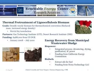
MODULAR HELIUM REACTOR DESIGN, TECHNOLOGY AND APPLICATIONS. Presented at UCSD Center for Energy Research Arkal Shenoy, Ph.D Director, Modular Helium Reactors General Atomics, San Diego shenoy@gat.com April, 2007. THE WORLD HAS AN ENERGY PROBLEM.

E N D
MODULAR HELIUM REACTOR DESIGN, TECHNOLOGY AND APPLICATIONS Presented at UCSD Center for Energy Research Arkal Shenoy, Ph.D Director, Modular Helium Reactors General Atomics, San Diego shenoy@gat.com April, 2007
THE WORLD HAS AN ENERGY PROBLEM • Fossil fuels provide 86% of US energy needs (80% of world needs), and are vital to meet this demand: • US oil consumption is over 20 million barrels daily (76 million worldwide): • BUT.. world LIQUID oil reserves will be declining, with a potentially • disastrous economic impact. • AND.. fossil fuels are the major man-made contributor to CO2 build up • in the atmosphere. With strong evidence that this is causing a world-wide • temperature increase via the “greenhouse” effect.
GT-MHR / LWR COMPARISON ItemGT-MHRLWR Moderator Graphite Water Coolant Helium Water Avg coolant exit temp. 850° - 1000 °C 310°C Structural material Graphite Steel Fuel clad Graphite & silicon Zircaloy Fuel UCO UO2 Fuel damage temperature >2000°C 1260°C Power density, w/cc 6.5 58 - 105 Linear heat rate, kW/ft 1.6 19 Avg neutron energy, eV 0.22 0.17 Migration length, cms 57 6
ADDED PLANT USER REQUIREMENTS • Plant sizes 300-1200 MW(e) range • Equivalent availability >90% • Meet existing safety and licensing criteria with no public sheltering • 10% power cost advantage over fossil fuel plants
MHR Design Features Are Well Suited for Significant Expansion of Nuclear Energy • Passive Safety • No active safety systems required • No evacuation plans required • Competitive Economics • High Thermal Efficiency • Siting Flexibility • Lower waste heat rejection, reduced water cooling requirements • High-Temperature Capability with Flexible Energy Outputs • Electricity • Hydrogen • Synfuels, etc. • Flexible Fuel Cycles • LEU, HEU, Pu, TRU, Thorium
WHY MHR IS ANSWER TO ENERGY PROBLEM • Passive Safety. • Flexible Reactor size to meet power needs. • High Plant Efficiency using GT Cycle • Potential for Attractive Economics • Provides Security and Sabotage Protection • Environmental Benefits • Flexible fuel cycle to burn WPu and LWR Waste • Hydrogen and Other Process heat Applications • Broad Technology Base exists --International cooperation • NGNP/NHDD Demonstrations will provide the Energy Option
Pyrolytic Carbon Silicon Carbide Porous Carbon Buffer Uranium Oxycarbide TRISO Coated fuel particles (left) are formed into fuel rods (center) and inserted into graphite fuel elements (right). PARTICLES COMPACTS FUEL ELEMENTS 1. Exploits Passive Safety Approach • Ceramic fuel retains radioactive materials up to ~2000˚C • Heat removed passively without primary coolant • Coated particles stable to beyond maximum accident temperatures • Fuel temperatures remain below design limits during loss-of-cooling events
2. Flexible to Meet Different Power Needs 450 MW(t) 350 MW(t) 600 MW(t) 102 Columns 1020 Elements 66 Columns 660 Elements 84 Columns 840 Elements 25 MW(t) 19 Columns 57 Elements
FOUR MODULES COMPRISE STANDARD PLANT M-273(27) 2-18-02
BENEFITS OF MODULAR CONSTRUCTION • Less total capital funds at risk during construction period • Reduced interest during construction expense • Capability to better match generation capacity to load growth • Potential to operate fewer modules should load growth not materialize • Potential to add more modules should load demand increase
3. Electricity Generation Efficiency is Increased by the Direct Brayton Cycle
GAS TURBO- COMPRESSOR GENERATOR INTERMEDIATE HEAT EXCHANGER MODULAR HELIUM REACTOR HEAT RECOVERY BOILER STEAM TURBINE GENERATOR CIRCULATOR PRIMARY SYSTEM COMBINED CYCLE POWER CONVERSION SYSTEM Several PCU Variations are Being Considered • CCGT • InDirect Cycle • Needs IHX • Distributed PCU • GTHTR300 • Direct Cycle • Horizontal PCU • Distributed PCU • GT-MHR • Direct Cycle • Vertical PCU • Integrated PCU
4. COMPARATIVE BUSBAR GENERATION COST • Improved Economics • Significantly higher efficiency • Elimination of all Active Safety systems • Significantly reduced BOP systems
5. Modules Located in a Below Grade Silo • Electrical output 286 MW(e) per module • Each module includes Reactor System and Power Conversion System • Reactor System 600 MW(t), 102 column, annular core, hexagonal prismatic blocks, very similar to successful FSV tests • Power Conversion System includes generator, turbine, compressors on single shaft, surrounded by recuperator, pre-cooler and inter-cooler • Natural sabotage protection Grade level Reactor building
7. With Deep Burn MHRs, Repository Lifetime Can Be Extended Dramatically, e.g., Yucca Mtn. 5000 250 1% nuclear electricity yearly growth 200 4000 200 3000 150 Power production (GWe) Power production (GWe) Waste Transuranic Actinides - TA - (tons) Present Strategy 100 2000 100 LWRs + MHRs + Deep Burn One-step 1000 50 YM Statutory Capacity Two-step 0 0 10 20 30 40 50 60 70 0 Time (years)
Deep Burn is a Promising Spent-Fuel Strategy, Based on MHR + TRISO Particle Fuel LWR waste TRISO Fab. Uranium Extraction • Spent fuel actinides made into TRISO fuel • Fissile Pu destroyed & actinides reduced in the DB-MHR • Spent TRISO elements placed in Repository • Coatings secure ~106 yrs. • With once-through Deep Burn processing • Little fissile Pu in Repository • Radio-nuclides permanently confined in TRISO particles • YM capacity greatly increased U, FP Fuel from Pu & Minor Actinides Deep Burn MHR Spent TRISO to Repository
8. Process Heat Applications (JAERI)
REACTOR CORE • Fuel assembly blocks stacked into columns and doweled together • Gaps btween graphite columns allow refueling • Restrained vertically by metallic core support • Core columns free to expand/contract vertically • Restrained horizontallyt top and bottom • Contained by core barrel
HTGR TECHNOLOGY PROGRAM • MATERIALS • COMPONENTS • FUEL • CORE • PLANT TECHNOLOGY 9. BUILD ON EXISTING TECHNOLOGY BASE BROAD FOUNDATION OF HELIUM REACTOR TECHNOLOGY DEMONSTRATION OF BASIC HTGR TECHNOLOGY EXPERIMENTAL REACTORS DRAGON (U.K.) AVR (FRG) PEACH BOTTOM 1 (U.S.A.) FORT ST. VRAIN (U.S.A.) THTR (FRG) GT-MHR MODULAR HTGR CONCEPT LARGE INTEGRATED HTGR DESIGN DATA BASE
Two High-Temperature Helium-Cooled Reactors Are Currently Operating in Asia Prismatic-Block HTTR in Japan Pebble-Bed HTR-10 in China HTTR reached outlet temperature of 950°C at 30 MW on April 19, 2004.
MHR Needs Demonstration by NGNP at INL • High level of inherent safety, eliminating core melt without operator action • Brayton cycle power conversion system for high thermal efficiency • Once-through fuel cycle with reduced high level waste • Superior radionuclide retention for normal operation and long-term spent-fuel disposal • Preferred hydrogen production technique • Competitive electricity/hydrogen production costs (reduced equipment capital and O&M; high efficiency)
Low- enriched Uranium TRISO LWR Spent Fuel TRISO Thorium Utilization TRISO VHTR IS THE ANSWER Common reactor core Electricity TRISO fuel in fuel blocks Hydrogen Key is TRISO coated fuel