Download
1 / 18
190 likes | 370 Vues
Single Event Effects (SEE) Test Results on the Virtex-II Digital Clock Manager (DCM). Jason Moore 1 , Carl Carmichael 1 , Gary Swift 2 and Jeff George 3

E N D
Single Event Effects (SEE) Test Results on the Virtex-II Digital Clock Manager (DCM) Jason Moore1, Carl Carmichael1, Gary Swift2 and Jeff George3 1Xilinx Corporation, San Jose CA 951242Jet Propulsion Laboratory / Caltech, Pasadena CA, 911093The Aerospace Corporation, El Segundo CA, USA "This work was carried out in part by the Jet Propulsion Laboratory, California Institute of Technology, under contract with the National Aeronautics and Space Administration." "Reference herein to any specific commercial product, process, or service by trade name, trademark, manufacturer, or otherwise, does not constitute or imply its endorsement by the United States Government or the Jet Propulsion Laboratory, California Institute of Technology." 1
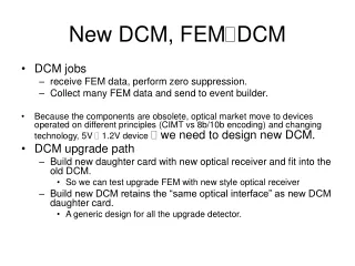
DCM CLK0 CLKIN CLK90 CLKFB CLK180 RST CLK270 CLK2X DSSEN CLK2X180 CLKDV PSINCDEC PSEN CLKFX PSCLK CLKFX180 LOCKED STATUS[7:0] PSDONE DCM Functionality • What is a DCM? • Digital Clock Manager • Embedded digital “dedicated” function in the FPGA that is configurable. • Delay-Locked Loop • Clock phase de-skew • Improves device Tcko • Duty cycle correction • Temperature compensation • Frequency Synthesis • CLKFX = CLKIN * (M/D) • Phase Shift • Fixed or Variable Mode • Resolution = 1/256 * period OR resolution of tap (~50ps) Clock signal Control signal 2
DCM BUFG DCM Functionality • Why use a DCM? • Most common function is the removal of clock insertion delay • Tcko of FPGA without a DCM • Tcko(FPGA) = Insertion Delay + Tcko (FF) + Data Delay • Tcko of FPGA with a DCM • Tcko(FPGA) = Tcko (FF) + Data Delay • Clock at pad of FPGA and internal FFs are aligned • This configuration was chosen for testing Clock Path: clk to a_14(FF) Location Delay type Delay(ns) Logical Resource(s) ------------ --------------- ------------- ------------------- D12.I Tiopi 0.653 clk (dcm_comp_CLKIN_IBUFG_INST) DCM_X0Y1.CLKIN net (fanout=1) 0.633 dcm_comp_CLKIN_IBUFG_OUT DCM_X0Y1.CLK0 Tdcmino -3.741 dcm_comp_DCM_INST BUFGMUX7P.I0 net (fanout=1) 0.674 dcm_comp_CLK0_BUF BUFGMUX7P.O Tgi0o 0.465 dcm_comp_CLK0_BUFG_INST U10.ICLK1 net (fanout=55) 0.742 clk_int ------------------------------------------------------------------------------------------------------------------------ Removal of Clock Insertion Delay Significant Impact on High-Speed Designs! 3
DCM Radiation Test Strategy • Elementary Tests • How hard is the DCM to upset? • SEUPI1 Analysis= 166 Configuration Memory Cells / DCM • Empirical Analysis = 160 Configuration Memory Cells (2 are unused) • What common error modes are observed? • Advanced Tests • Detailed analysis of error modes • Mitigation Evaluation • DCM Configurations • Not every permutation and combination of DCM options tested • Focused on most common applications • CLK0 and CLKFX 1: Single Event Upset Probability Indicator 4
Virtex-II Radiation Test Platform CONFIGMON SW CONFIGMON HW • Functional Monitor/Control : FUNCMON • User-Specific Functionality (e.g. DCM, I/O, Multipliers, etc) • Configuration Monitor/Control : CONFIGMON • Common Configuration Logic • Scrubbing; Readback for SEFI Detection Virtex-II “SEAKR Board” FUNCMON SW FUNCMON HW Service FPGA DUT FPGA 2V3000 2V6000 5
Virtex-II Radiation Test Board JTAG I/F DUT FPGA Service PROMs DUT PROMS (design and mask) Service FPGA 6
DCM BUFG Elementary DCM Test • November ’03 : Texas A&M Cyclotron • Focus on Cross-Section Calculations • Focus on Common Error Modes • Device Under Test (DUT) FPGA Design • CLK0 de-skew : Most common application • Six DCMs tested simultaneously • Scrubbing configuration memory continuously • Service FPGA Design • Basic Concept : Compare the output of three counters • Counters operate at 100MHz • Two “Radiation” Counters, One “Golden” Counter • Error Modes Detected • “Stuck At”, Transients and Change in Frequency 7
Elementary DCM Test Design Details reset OSC IBUFG DCM • Redundant outputs from the DUT DCM allow detection of I/O errors • Routing errors are included in the DCM error analysis (worst case) • Error Detection and Reporting Logic • Asynchronous FIFOs used to transfer count values across clock domains • Dual-Port RAMs used to store status register values • Upon every error, a flag is set and the values of LOCKED and STATUS(1) are recorded SERVICE FPGA DUT FPGA CLKIN To DUT DCMs (top) OBUF CLKFX DCM 3x MULT = 100MHz All clocks CLKIN IBUFG CLKFB CLK0 BUFG CLKIN OBUF To DUT DCMs (bot) CLKFX (x6) DCM RST STATUS DCMreset LOCK BUFG CLKIN Error Detection and Reporting (x6) CLK0 Status Registers BUFG IO Fail Count CLKFX DCM Fail Count CLKFB Golden Clock DCM Data A Radiation Clocks DCM Data B DCM Data C 8
Elementary DCM TestResults • Cross-Section Results • 40.0 MeV/u Ne, LET=1.22 MeV/cm2/mg • Cross Section: 8e-9 cm2/DCM • Need more visibility into Error Detection and Correction • Understanding of Mitigation Methods • Reset vs Scrub vs Reset and Scrub • Error Detection: Is LOCKED a reliable status? 9
Advanced DCM Tests • June and August ’04 : Texas A&M Cyclotron • Multiple LETs and Ions • Ne, Ar, Kr, • 1.28, 4.28, 18.1 and 35.1 (MeV/mg/cm2) • Provided more User Control • Added Control FSM : User dictates Reset or Scrub command • Detailed Error Logging • Which errors are corrected by • Reset • Scrub • Scrub and Reset • 2nd and 3rd DUT Configurations Created • CLKFX output • CLK0 output at slower frequencies 10
Device Under Test Configurations • DUT DCM Configuration • CLK0 w/feedback • 100MHz in and out (“CLK0FAST”) • 33MHz in and out (“CLK0SLOW”) • DUT DCM Configuration • CLKFX w/ CLK0 feedback • 33MHz in -> 100MHz out • “CLKFX” DCM1 DCM2 DCM3 33MHz or 100MHz CLK0 BUFG BUFG 33MHz or 100MHz 100MHz CLKFX 33MHz BUFG DCM DCM DCM4 DCM5 DCM6 11
DCM Control “Reset Only” Data Path Errors Scrub required Configuration Errors • Test Operator has complete control of Correction Method • Reset, Scrub, Scrub and Reset • Scrub • Refresh of configuration memory while operating • Reset • DCM Reset Only Not fixed Not fixed Wait for DCM Error Reset DCM Scrub DCM Reset DCM fixed fixed fixed 12
DCM Functional Monitor SW Logging Run/Error Status Per DCM Control and Status User Controlled Reset Real-time value of LOCKED output 13
Cross-Section Results • DCM CLK0 and CLKFX outputs have “statistically equivalent” susceptibility 14
Cross-Section Results • No evidence of SET effects on the DCM between 33 and 100MHz. 15
Cross-Section Analysis • Large % of errors at a high LET are in the datapath • DCM reset is all that is required to restore operation • 20-120us LOCK time (CLK0) • 10ms LOCK time (CLKFX) • DCM Configuration Cell Usage is consistent • ~38% (60 of 160) of the DCM Configuration Cells are critical for the CLKFX and CLK0 designs. 16
Lessons Learned andFuture Work • Lessons Learned • “Elementary Tests” are not efficient or cost effective • Development of Fault Injection capabilities will eliminate the need for beam time during the early stages of SEU evaluation • Future Work • Analysis and test of self-EDAC logic • Autonomous Detection and Correction using XTMR 17
Summary • Results • The “saturated” DCM Cross-Section is ~1e-5 • CLK0 and CLKFX Configuration Bit exposure is ~60 bits • Data Path Errors dominate at LET > 5 MeV/cm2/mg • Only a reset is required to resynchronize DCM • No apparent frequency dependence from 33MHz to 100MHz • DCM LOCKED output is not a reliable indicator of upsets • Scrubbing the DCM does not disturb the LOCK signal • An SEU in the DCM will not cause a functional failure of the if the Xilinx Triple Module Redundancy method is employed. 18