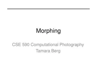
2D preobrazba (morphing)
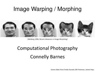
2D preobrazba (morphing). 2D preobrazba dekle-tiger. Princip 2D preobrazbe. Uvod. Morphing – derived from the word metamorphosis. Metamorphosis means to change shape, appearance or form.Example:. Kaj je preobrazba ?.


2D preobrazba (morphing)
E N D
Presentation Transcript
Uvod • Morphing – derived from the word metamorphosis. • Metamorphosis means to change shape, appearance or form.Example:
Kaj je preobrazba? • Morphing can be defined as: - Transition from one object to another. - Process of transforming one image into another. • An animation technique that allows you to blend two still images, creating a sequence of in – between pictures that when played in Quick Time, metamorphoses the first image into the second.
Kaj je preobrazba slike? • Creating a smooth transition between two images • 3D model based or Image based • Used for obtaining special effects
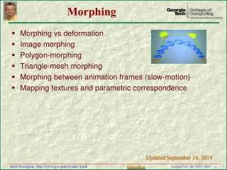
Tehnike preobrazbe slike • Cross-dissolve • Field morphing • Mesh morphing • Radial Basis Functions (RBF) • Energy minimization • Multilevel Free-Form Deformation (MFFD)
Cross-Dissolve • Pixel-by-pixel color interpolation • Very primitive • Not smooth transitions
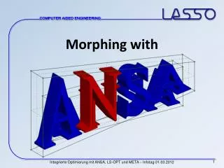
Mesh Warping • Source and target images are meshed • The meshes for both images are interpolated • The intermediate images are cross-dissolved
Mesh Warping • for each frame f do • Linearly interpolate mesh M, between Ms and Mt • warp Images to I1, using meshes Ms and M • warp Imaget to I2, using meshes Mt and M • Linearly interpolate image I1 and I2 • end
Mesh Warping • Hard to fit the mesh in images • All control points affect the warping equally • Not enough control in certain areas when needed
Image morphing • Coordinate grid approach • Define curvilinear grid on both images • Take care of grid-to-grid correspondences • A curved mesh is then generated using the grid intersection points as control points for an interpolation scheme such as Catmull-Rom splines.
Coordinate Grid Approach • Interpolate vertices to get intermediate grid • Create two images by stretching pixels • Cross dissolve the two
Image morphing details • Two pass scheme. First pass: • Auxiliary grid is created by taking x’s from first, y’s from intermediate • For each scanline: • Get curve intersections • These define separate stretches • Get pixel range for each stretch • Result is passes to the second pass (over columns)
Aux grid Auxiliary image Original 1 (take x’s) Intermediate Image (take y’s)
Aux grid Auxiliary image Fit a spline (Catmull-Rom) Original 1 Intermediate Image
Pixel splatting (for each scanline) original pixels Grid coords intersections 3 2 1 0 Pixel coords Fit a spline 3 2 1 0
For given pixel in the auxiliary image, determine the range of pixel coordinates in the source image For example, pixel 6 of auxiliary grid maps to pixel coordinates 3.1 to 5.5 of image
Establishing the auxiliary pixel range for a pixel of the intermediate image. For example, pixel 6 of the intermediate grid maps to pixel coordinates 3.1 to 5.5 of the auxiliary image.
Feature-based morphing • Want to use just a set of features • Rather than complete grid • Feature = line drawn on the image • Form intermediate feature image • Simple interpolation of features • Center/orientation or endpoints • Map each pixel to each interpolated feature • Compute associated weight
Feature-Based Warping • “Which pixel coordinate in the source image do we sample for each pixel in destination image?” • Correspondence achieved using feature line(s) in source and destination images
Feature-Based Warping • Transformation with one pair with features(lines) • Transformation with multiple pairs of features(lines)
Transformation with One Pair of Lines • A pair of features(lines) – one defined relative to the source image while the other defined relative to destination image • A pair of lines defines a coordinate mapping from destination pixel (denoted X)to source pixel(denoted X’)
Transformation with One Pair of Lines • For each pixel X in the destination image • Find the corresponding u, v • Find the X’ in the source image for that u, v • destinationImage(X) = sourceImage(X’)
Transformation with One Pair of Lines • Equation: X, X’ represent for pixel of destination and source image. PQ, P’Q’ denote line segments and u, v stand for scalars u = (X-P)•(Q-P) / ||Q-P||^2 v = (X-P)• Perpendicular(Q-P) / ||Q-P|| X’ = P’ + u(Q’-P’) + v*Perpendicular(Q’-P’) / ||Q’-P’||
Transformation with One Pair of Lines • Original image (UL), rotated image (UR), translated image(LL), scaled image (LR)
Weighting Effect of Each Line Pair • a – smoothness of warping • b – falloff of strength with distance • p – rewarding longer lines
Transformation with Multiple Pairs of Lines • For each pixel X in destination • DSUM=(0,0) • weightsum=0 • For each line Pi Qi • Calculate u,v based on Pi Qi • Calculate X’I based on u,v and Pi’ Qi’ • Calculate displacement Di=Xi’-Xi • Calculate weight • DSUM+=Di*weight; weightsum+=weight • X’ = X+ DSUM/weightsum • destinationImage(X) = SourceImage(X’)