Download

1 / 49
491 likes | 837 Vues
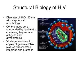
Automation of Hanging Drop Crystallization Joel Bard Structural Biology Wyeth Research Cambridge, Massachusetts USA. Why Automate?. Higher Throughput - Freeing crystallographers and research associates from setting up drops allows them to devote more effort to

E N D
Automation of Hanging Drop Crystallization Joel Bard Structural Biology Wyeth Research Cambridge, Massachusetts USA
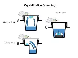
Why Automate? Higher Throughput - Freeing crystallographers and research associates from setting up drops allows them to devote more effort to issues that require human input. - More conditions = More crystals. - Handle more projects without increased personnel Why Hanging Drop? Proven Technology -Most commonly used method -Greatest experience base -Ease of imaging -Crystals easily recovered -Individually sealed wells
Functional Objectives - We are not a Structural Genomics Center - Smaller number of projects - High success rate required - Flexibility and reproducibility more important than throughput - Capacity must be sufficient for a group of 8 crystallographers working on ~25 projects - System must be suitable for both screening and optimization - System must be user friendly so that all group members can operate it without extensive training.
Implementation Hardware- Well Solutions - Packard Multiprobe Drop Solutions - Cartesian Honeybee HD Imaging - CRS F3 Robot Arm Nikon E1000 Compound Microscope Prior H101 Motorized Stage Roper Coolsnap and QImaging Micropublisher CCD Cameras Software- Data management & Experimental Design - RoCKS - Robotic Crystallization Knowledge System, custom developed in collaboration with Formulatrix serving as a front end for MS SQL Server Image Acquisition - Scanalytics IPLab
48 Well Pre-Greased Plates and 12 mm Circular Glass Coverslips for Hanging Drop (Hampton Research) The 48 well format was chosen to allow reasonably comfortable human manipulation of the coverslips for crystal recovery or seeding experiments.
Honeybee HD Workspace Pick and Place Dispensers Coverslip Magazine Drying Washing Protein Stock Plate Holder
Aspirate Protein Pre-pressurize Pre-dispense 1 Pre-dispense 2 Pre-dispense 3 – Dispenses get smaller until equilibrium is reached. Aspirate Airgap Syringe Pump Tubing Basics of SynQUAD Function Valve Ceramic Tip
Dispensing Highly Viscous Well Solutions If all dispensing parameters are not optimized, the droplet may stick to the tip. Valve open time appears to be the critical parameter. The tip must be thoroughly washed and dried during the predispensing phase. Adequate vacuum in the drying system must be maintained. Currently 0.5 uL dispenses of 25% PEG 8000 are essentially always successful.
Protein Dispensing Issues Airgap size Predispense volume Whether to aspirate for each pair of rows or for entire plate. Maintainance of valve integrity
Syringe Pump To Small an Airgap – Protein mixes with backing solution and gets diluted. Tubing Valve Ceramic Tip
Effect of Predispense Volume on Dispense Volume Consistency Insufficient Predispensing – 4 uL Improved – 5 uL
Syringe Pump Tubing Problems with air in the valve: Dispense fails because air bubble interferes with valve function. Solutions: 1. Limit protein aspiration volume to keep the airgap below the valve. 2. Aspirate extra protein so that the air gap never reaches the valve. Extra protein is returned to vial after the tray is complete. Valve Ceramic Tip
Maintaining Valve Integrity If protein is to be aspirated beyond the valve, great care must be taken that the system is washed very thoroughly afterwards to maintain valve integrity. Two washes: 1 M Acetic Acid - Removes protein 100% Methanol - Dislodges air bubbles Our software chooses whether to aspirate beyond the valve based on the volume of protein being dispensed and automatically incorporates extra wash steps if needed. For smaller drop volumes, protein is aspirated for each pair of rows and kept below the valve. For larger drop volumes, protein is aspirated once for the entire tray and goes beyond the valve. Because of the additional washing steps, throughput is reduced from 15 min/tray to 20 min/tray when protein is aspirated beyond the valve.
Coverslip Handling Mechanism Pick and Place Suction Cups Magazine Coverslips Lifters
Suction cups are lowered into magazine
Lifters raise coverslips to meet suction cups
Vacuum is applied and suction cups are partially raised
Shake Pick and Place is shaken to release coverslips which may have stuck together.
Coverslips are raised to clear magazine
Pick and Place rotates to present coverslips for dispensing
Coverslip Handling Issues Stacks must be of similar heights to ensure that all of the suction cups can reach their stacks at the same time. There is some leeway, though. Suction cups must be kept clean and vacuum lines kept unclogged. Coverslip quality control was an issue at first: Coverslips must be within fairly strict size and shape tolerances. Off-round or too-large coverslips can impede movement of the stacks within the magazine. Coating must be sufficient to cause the drop to bead properly but excess coating causes the coverslips to stick to each other too strongly. Coverslips must be supplied dust free. Hampton developed new packaging to isolate the foam padding.
Crystallization Project Flow in RoCKS Details for each Project, Construct, Protein Prep, and Compound are stored in a central database which is accessible from all workstations.
Screening Screening conditions are selected from among standard commercial kits and custom cocktails
The Multiprobe is used to fill 48 Well Pre-Greased Plates from 96 tube racks. Racks have covers which seal all tubes simultaneously (no screw caps).
Automated Image Acquisition Digital images are acquired with a compound microscope using a 4X objective. Plates are delivered to the microscope by a CRS F3 robotic arm. Tray ID numbers read from the barcode are passed to the IPLab acquisition software. 11 focus slices are acquired for each well. Images are transferred to a terabyte RAID array and compressed. References to the images are stored in the RoCKS database. The best focused image from each stack is determined automatically but all images are stored. We will soon be generating deep focus montages for each well.
Issues in Image Acquisition: Optics Compound vs. Stereo Microscope Optimization of optics Optimization of Image Display
Choice of Optical System Compound Microscope Stereo Microscope
Optimizing Optics for Imaging Drops Bad Dark Ring Better Higher Numerical Aperture Objective Objective Drop Well Long Working Distance Condenser Condenser
Monitor Calibration Gamma = 1.0 Gamma = 1.8 Proper adjustment of the Gamma function which relates bitmap pixel values to the actual values displayed on the monitor is essential for the preservation of subtle detail.
Effect of Gamma on Visibility of Detail Gamma 1.0 Gamma 1.8
Issues in Image Acquisition: Drop Position in 3 Dimensions Drop position on the coverslip is quite consistent. The position of the coverslip on the well can vary substantially in Z and slightly in XY because of difficulty of automatically placing a thin piece of glass on a viscous platform in a completely consistent fashion. Solutions: Use a large CCD chip and low magnification to account for XY variability. Acquire a wide range of slices along the Z axis. Both of these solutions increase image storage requirements. We have found that 10 fold jpeg compression does not significantly degrade the usefulness of the images for human inspection. Smaller files can also be retrieved for viewing at a workstation more quickly.
RoCKS Image Viewing and Scoring: Image View Up/Down arrow keys move between images in the Z stack, like focussing a microscope.
Full Resolution of 1392 X 1040 compressed image Not too bad but we’re installing a 3 megapixel camera
Optimization with RoCKS and the Honeybee SD When a promising condition is identified in a screen, it can easily be imported into three optimization modules. Random Optimization -Randomly choose solutions from a defined space (e.g. Any PEG with a single buffer over a specific pH range) Grid Optimization in 3 Dimensions -Vary Concentration or pH of up to 3 ingredients systematically -Vary drop size or ratio of protein to well solution -Multiple grids on a single plate Additive Screens -Many additives with a single well solution -Honeybee SD adds additive to drop, not well Well Solutions for optimizations are automatically generated with the Multiprobe from a library of stock solutions.
Random Optimization This method allows sparse sampling of a region of crystallization space that is smaller than an initial screen but still too large for thorough inspection using grids. Ingredients are divided into groups such as precipitants, salts, buffers etc. The user selects which ingredients are to be included in each group and defines a range of concentrations and pH’s (for buffers) to be used for each ingredient. For each well, one ingredient from each group is randomly selected for inclusion in the well solution. The concentration or pH is also selected at random from within the range specified. The user can determine the relative probability of selecting a given ingredient from within its group. One can also leave a given ingredient group out completely in a specified fraction of the wells.
Grid Optimization: An optimization Tray Set can contain any number of Grids distributed over any number of trays. Grids can contain any number of rows, columns, and layers. Layers can correspond to trays but don’t have to. For example, a 3 row X 4 column X 4 layer grid will fit on a single tray. Any ingredient can vary in concentration (or pH if it’s a buffer) along any of these dimensions. The ratio of protein to well solution can be varied for any well.
Additive Screens This method allows one to find an additional ingredient which improves crystal quality once a promising well solution has been found. Additive solutions are provided in a 48 well tissue culture plate and placed in the two auxiliary plate holders on the Honeybee HD deck. Well solution is aspirated into one set of 8 synQUAD channels, additive solution is aspirated into the other set of 8 channels. Protein is handled as usual. This allows all 3 components of the drop to be dispensed in rapid succession. As a result, only half of each crystallization tray is used.
Additive Screen Protocol Aspirate Additives with Right Side Channels Aspirate Mother Liquor with Left Side Channels Aspirate Protein Dispense Mother Liquor Dispense Additive to Same Coverslips Dispense Protein
Clicking the Robot button on any of the optimization pages creates control files for the Honeybee HD and the Multiprobe II as well as HTML User Instructions. Stock solution positions are optimized to make efficient use of the eight tip Mutiprobe. Typical Grid Optimizations can be dispensed in < 10 minutes/plate by using as many as 8 tubes for each stock solution. Library of stock solutions arranged by ID numbers allows rapid setup of stock solution tube rack.
Multiprobe Pipetting Accuracy 50% PEG 8000 Aqueous Buffer
Crystallization Results with Hand vs. Robot A panel of 7 commercially available proteins (not including lysozyme!) were screened against 5 commercial screening kits by hand on glass and teflon and by robot using 2 different drop sizes. Interestingly, crystals often appeared in different conditions in screens set up by hand as opposed to by robot. Among all conditions where crystals were seen at all, only 35% had crystals in both hand and robot drops. Possible reasons: -Instantaneous mixing of protein and well solutions in robot -Differences in equilibration rate -Stochastic effects
Conclusions The Honeybee HD system has been in production use for ~6 months. Maximum throughput is ~1500 drops/day. Considerable effort has been put into making robot operation reliable and consistent. For standard screening, >99% of drops are dispensed successfully. We have confidence in screening results from the robot. That is, we feel that if crystals are not found in the robot screen we do not then have to repeat the screen by hand. Robot crystallization is different from hand crystallization. It is not always straightforward to move hits between one method and the other. Coupled with suitable software, this robotic system has the flexibility to perform all of the types of crystallization experiments that we have traditionally used in optimization.
Acknowledgements Wyeth Will Somers Rajiv Chopra Jasbir Seehra Kristine Svensen Meggin Taylor Andrea Olland Kimberly Ercolani Cartesian Michelle Rodriguez Hamid Khoja Rico Miledi Barbara McIntosh Formulatrix Jeremy Stevenson David Della Bitta CRS Robotics Brad Balaban James Fernandez Scanalytics Fernando Delaville Hampton Research Bob Cudney