Download
1 / 67
780 likes | 1.17k Vues
9. Semiconductors Optics. Absorption and gain in semiconductors Principle of semiconductor lasers (diode lasers) Low dimensional materials: Quantum wells, wires and dots Quantum cascade lasers Semiconductor detectors. Semiconductors Optics. Semiconductors in optics:

E N D
9. Semiconductors Optics • Absorption and gain in semiconductors • Principle of semiconductor lasers (diode lasers) • Low dimensional materials: • Quantum wells, wires and dots • Quantum cascade lasers • Semiconductor detectors
Semiconductors Optics • Semiconductors in optics: • Light emitters, including lasers and LEDs • Detectors • Amplifiers • Waveguides and switches • Absorbers and filters • Nonlinear crystals
The energy bands One atom Two interacting atoms N interacting atoms Eg
Insulator Conductor (metals) Semiconductors
Doped semiconductor p-type n-type
Interband transistion nanoseconds in GaAs
Intraband transitions < ps in GaAs n-type
UV Optical fiber communication
InP GaAs ZnSe
Bandgap rules The bandgap increases with decreasing lattice constant. The bandgap decreases with increasing temperature.
Interband vs Intraband C • Interband: • Most semiconductor devices operated based on the interband transitions, namely between the conduction and valence bands. • The devices are usually bipolar involving a p-n junction. V • Intraband: • A new class of devices, such as the quantum cascade lasers, are based on the transitions between the sub-bands in the conduction or valence bands. • The intraband devices are unipolar. • Faster than the intraband devices C
Interband transitions E Conduction band k Valence band
E Conduction band Eg k Valence band Examples: mc=0.08 me for conduction band in GaAs mc=0.46 me for valence band in GaAs
Direct vs. indirect band gap k k GaAs AlxGa1-xAs x<0.3 ZnSe Si AlAs Diamond
Direct vs. indirect band gap Direct bandgap materials: Strong luminescence Light emitters Detectors Direct bandgap materials: Weak or no luminescence Detectors
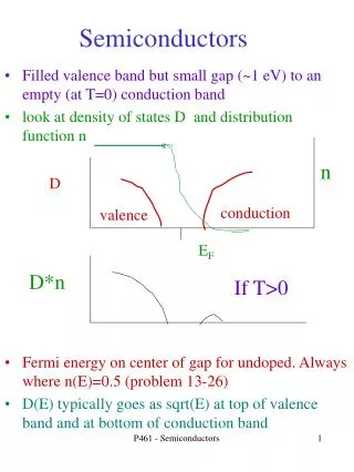
Fermi-Dirac distribution function E 0.5 1 EF f(E)
Fermi-Dirac distribution function For electrons For holes E 0.5 1 EF kT f(E) kT=25 meV at 300 K
Fermi-Dirac distribution function For electrons For holes E f(E) 0.5 1 EF kT kT=25 meV at 300 K
E Conduction band Valence band
E Conduction band Valence band For filling purpose, the smaller the effective mass the better.
Where is the Fermi Level ? E Conduction band n-doped Intrinsic Valence band P-doped
Interband carrier recombination time (lifetime) ~ nanoseconds in III-V compound (GaAs, InGaAsP) ~ microseconds in silicon Speed, energy storage,
Quasi-Fermi levels E E E Ef e Immediately after Absorbing photons Returning to thermal equilibrium Ef h
E fe # of carriers EF e x = EF h
E Condition for net gain >0 EF c Eg EF v
P-n junction unbiased EF
P-n junction Under forward bias EF
Heterojunction Under forward bias
Homojunction hv N p
Heterojunction waveguide n x
Heterojunction 10 – 100 nm EF
Heterojunction A four-level system 10 – 100 nm Phonons
Absorption and gain in semiconductor g Eg E
Absorption (loss) g Eg Eg
Gain g Eg Eg
Gain at 0 K Eg EFc-EFv g EFc-EFv Eg Density of states
Gain and loss at 0 K g EF=(EFc-EFv) Eg E=hv
Gain and loss at T=0 K at different pumping rates g EF=(EFc-EFv) Eg E N1 N2 >N1
Gain and loss at T>0 K laser g Eg N2 >N1 N1 E
Gain and loss at T>0 K Effect of increasing temperature laser g Eg N2 >N1 N1 E At a higher temperature
A diode laser Larger bandgap (and lower index ) materials <0.2m p n <0.1 mm Substrate Cleaved facets w/wo coating Smaller bandgap (and higher index ) materials <1 mm
Wavelength of diode lasers • Broad band width (>200 nm) • Wavelength selection by grating • Temperature tuning in a small range
A distributed-feedback diode laser with imbedded grating <0.2m p n Grating
Typical numbers for optical gain: Gain coefficient at threshold: 20 cm-1 Carrier density: 10 18 cm-3 Electrical to optical conversion efficiency: >30% Internal quantum efficiency >90% Power of optical damage 106W/cm2 Modulation bandwidth >10 GHz
Semiconductor vs solid-state Semiconductors: • Fast: due to short excited state lifetime ( ns) • Direct electrical pumping • Broad bandwidth • Lack of energy storage • Low damage threshold Solid-state lasers, such as rare-earth ion based: • Need optical pumping • Long storage time for high peak power • High damage threshold
Strained layer and bandgap engineering Substrate
Density of states 3-D (bulk) E
Low dimensional semiconductors When the dimension of potential well is comparable to the deBroglie wavelength of electrons and holes. Lz<10nm