Microcontroller Programming I MP5- 1
Microcontroller Programming I MP5- 1. Microcontroller Programming I MP5- 2. Digital input, digital output. - Most straight forward task for a microcontroller: Detecting the state of a binary sensor ( digital input ) and switching things on and off ( digital output ).

Microcontroller Programming I MP5- 1
E N D
Presentation Transcript
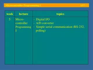
Microcontroller Programming I MP5-2 Digital input, digital output - Most straight forward task for a microcontroller:Detecting the state of a binary sensor (digital input) and switching things on and off (digital output) - All microcontrollers have a certain number of digital I/O lines which can be configured as inputs or as outputs; the output driver can be either open-collector/open-drain or push-pull (TTL); sometimes, either variant can be selected - When a pin is configured as input, the corresponding output drivers are switched tri-state (also: hi-Z, high-impedance switched off)
Microcontroller Programming I MP5-3 Digital input, digital output - To configure a pin as input or output, the Data Direction Register (DDR) has to be programmed; each bit corresponds to one of the I/O lines of the controller; frequently, programming a ‘1’ makes the corresponding I/O line act as output, a ‘0’ produces an input; the reset value is commonly ‘0’ (input) - The state of an output line depends on the associated output (latch) register; each bit corresponds to a single pin on the microcontroller - The logic level of an input line can be determined by reading the corresponding input register
Microcontroller Programming I MP5-4 Digital input, digital output - For information on digital I/O, search the user manual of the microcontroller for I/O ports or General Purpose I/O Example: Infineon C167CR-LMChapter 7: Parallel Ports
Microcontroller Programming I MP5-5 Digital input, digital output - The digital I/O unit of the C167CR features a variety of 8-bit and 16-bit ports, each of which is controlled by 2/3 Special Function Registers (SFR)
Microcontroller Programming I MP5-6 Digital input, digital output - Every port has its own data register (Px or PxH, PxL, where x = 0 … 8); each bit of a data register corresponds to a different I/O line - The data direction (input or output) of an I/O line is defined in the direction control register (DPx or DPxH/L); port 5 is always an input and therefore does not need a direction control register - Ports 2, 3 and 6 – 8 can specify the output driver to be used (push-pull or open-drain); the SFR which controls this is called Output Driver Control register (ODx)
Microcontroller Programming I MP5-7 Digital input, digital output - Example:Switch-on an array of LEDs conntected to pin 1 – 4 of port 2 and read the states of a pair of switches connected to pin 7 and 8 of the same port 5V PORT2 0V
15 0input output Microcontroller Programming I MP5-8 Digital input, digital output (1) Need to program bits 1 – 4 of port 2 as output while ensuring that bits 7 and 8 remain inputs (2) Should change output driver constellation from push-pull to open-collector (safer) (3) Need to set bits 1 – 4 to ‘1’ (line: logical high, output voltage: 5 V) (4) Need poll state of bits 7, 8 of port 2 (inputs)
Microcontroller Programming I MP5-9 Digital input, digital output #include <reg167.h> void main (void) { unsigned int sw7, sw8; /* store input states here */ DP2 = 0x001E; /* I/O lines 1 – 4 : outputs */ ODP2 = 0x001E; /* output drivers : open-drain */ P2 = 0x0000; /* switch LEDs on (active low) */ while (1) { /* loop forever */ sw7 = P2 & 0x0080; /* read P2, filter out bit 7 */ sw7 = (sw7 != 0); /* sw7 is '1' if switch pressed */ sw8 = P2 & 0x0100; /* read P2, filter out bit 8 */ sw8 = (sw8 != 0); /* sw8 is '1' if switch pressed */ } /* while(1) */ } /* main */ Note: the LEDs switch on when the port is driven low (ACHTUNG! Limit the current…)
Microcontroller Programming I MP5-10 Digital input, digital output Start the simulator and go till main open Port 2 and single step through the program
Microcontroller Programming I MP5-11 Digital input, digital output Lines 1 – 4 become outputs with open-drain o/p drivers sw7 and sw8 are both off
Microcontroller Programming I MP5-12 Digital input, digital output Set line 7 to high; the data register P2 does not reflect this! sw7 and sw8 are both on!?!
Microcontroller Programming I MP5-13 Digital input, digital output - This should be surprising – sw8 seems to follow whatever happens to sw7 (and vice versa)! - To find the reason for this strange behaviour it is advisable to switch the display from source code only to mixed source and disassembly code - Single-stepping through the code reveals that sw7 and sw8 are both kept in the same register (R5) which is not saved but simply overwritten when the next value needs to be stored; this is why both variables appear as one – because they are
Microcontroller Programming I MP5-14 Digital input, digital output Variables sw7 and sw8 are so-called automatic variables; they are often kept in registers
Microcontroller Programming I MP5-15 Digital input, digital output - During compilation, the optimiser of the C166 compiler recognizes that sw7 and sw8 are both assigned values which are never used (i. e. they are never compared to anything or manipulated in any way); it therefore assigns both of these automatic variables to the same general purpose register (R5) - There are a number of ways this possibly unwanted behaviour can be avoided: The most straight forward solution is to use sw7 in a subsequent manipulation or comparison; its value must therefore be maintained while working on sw8…
Microcontroller Programming I MP5-16 Digital input, digital output #include <reg167.h> void main (void) { unsigned int sw7, sw8; /* store input states here */ DP2 = 0x001E; /* I/O lines 1 – 4 : outputs */ ODP2 = 0x001E; /* output drivers : open-drain */ P2 = 0x0000; /* switch LEDs on (active low) */ while (1) { /* loop forever */ sw7 = P2 & 0x0080; /* read P2, filter out bit 7 */ sw7 = (sw7 != 0); /* sw7 is '1' if switch pressed */ sw8 = P2 & 0x0100; /* read P2, filter out bit 8 */ sw8 = (sw8 != 0); /* sw8 is '1' if switch pressed */ if(sw7 == 1) P2 = P2 | 0x0001; /* switch off LED1 */ else P2 = P2 & ~0x0001; /* switch on LED1 */ } /* while(1) */ } /* main */ Using sw7 after sw8 the compiler needs to maintain its contents
Microcontroller Programming I MP5-17 Digital input, digital output sw7 is now stored in R5, sw8 is stored in R7 P2 now reflects the state of the line!?!
Microcontroller Programming I MP5-18 Digital input, digital output - The parallel port display window of the simulator shows the state of the associated output latch (P2), the state of the direction control register, the state of the output driver control register and the line status - The output latch only changes when the port register is written to; this is what is done now:if(sw7 == 1) P2 = P2 | 0x0001; else P2 = P2 & ~0x0001; Writing to output latch Reading from input latch
Microcontroller Programming I MP5-19 Digital input, digital output • Setting a bit in C:P2 = P2 |0x0001; Logical OR operator Mask • Example: P2 contains value 0x1234P2 = 0001.0010.0011.0100 P2 = P2 |0000.0000.0000.0001 P2 = 0001.0010.0011.0101 • The above line can be abbreviated as follows:P2 |=0x0001;
Clearing a bit in C: Logical NOT operatorP2 = P2 &~0x0001; Logical AND operator Mask • Example: P2 contains value 0x1234P2 = 0001.0010.0011.0100 P2 = P2 |~0000.0000.0000.0001P2 = 0001.0010.0011.0100 P2 = P2 |1111.1111.1111.1110P2 = 0001.0010.0011.0100 Microcontroller Programming I MP5-20 Digital input, digital output • The above line can be abbreviated as follows:P2 &=~0x0001;
Microcontroller Programming I MP5-21 Digital input, digital output - A less intrusive way of avoiding an unwanted ‘optimization’ of automatic variables is by modifying the optimization options of the compiler In the C166 compiler options menu a level of code optimization can be selected; choosing level ‘2’ avoids the use of register variables
Microcontroller Programming I MP5-22 Digital input, digital output sw7 and sw8 are now kept at different addresses on the user stack;user stack pointer: R0
Microcontroller Programming I MP5-23 Digital input, digital output - A more direct way of keeping sw7 and sw8 separate is to declare their storage class as ‘static’:static unsigned int sw7, sw8; - This informs the compiler that sw7and sw8 are to be assigned their own individual space in memory - As we are working with a SMALL memory model, these variables will end up in near memory (object class NDATA); access to sw7 and sw8 will thus be implemented using Data-Page Pointers (DPP)
Microcontroller Programming I MP5-24 Digital input, digital output sw7 and sw8 are now static and as such are allocated their own space in memory:DPP2:0x1002andDPP2:0x1000
Microcontroller Programming I MP5-25 Digital input, digital output - The most elegant way of keeping sw7and sw8 separate is to declare them using the scope modifier ‘volatile’:unsigned int volatile sw7, sw8; - This informs the compiler that sw7and sw8 are ‘volatile’ in nature, i. e. their contents can be modified from outside their scope (e.g. by an interrupt routine) - The optimiser is therefore stopped from assuming that the contents of sw7 and sw8 are never used
Microcontroller Programming I MP5-26 Digital input, digital output automatic variables sw7 and sw8 have been declared volatile and thus are not optimised away…
Microcontroller Programming I MP5-27 Storage class specifiers [1] - The term storage class refers to the method by which an object is assigned space in memory; common storage classes are static, automatic and external - Static variables are given space in memory, at some fixed location within the program. Its value is faithfully maintained until we change it deliberately - Automaticvariables are dynamically allocated on the user stack when the block they are defined in is entered; they are discarded when this block is left - The externalstorage class is used for objects that are defined outside the present source module
Microcontroller Programming I MP5-28 Storage class specifiers: static - Making a global variable static limits its scope to the file it is defined in - Static local variables are allocated their permanent storage location in RAM, unlike non-static local (automatic) variables which are created on the user stack; they thus retain their value from one instance of a function call to the next - The assembly language name of the static local is a unique compiler-generated name (e.g. L1, L2, …); this allow the same C-language variable name to be used in different functions
void main (void) {static unsigned int myLocal; myLocal = 100;} void main (void) {unsigned int myLocal; myLocal = 100;} ADD R0,#0xFFFE MOV R4,#0x0064 MOV [R0],R4 ADD R0,#2 MOV R4,#0x0064 MOV DPP2:0x1000,R4 Now a fixed address Microcontroller Programming I MP5-29 Storage class specifiers: static • Example: - Note that static variables can be made read-only by adding the modifier const; the linker commonly places these variables in ROM
Microcontroller Programming I MP5-30 Storage class specifiers: automatic - Automatic variables are only required temporarily; they are local and only exist during the lifespan of the currently executed block - If a function has automatic variables, the compiler generates instructions which – upon entry to this function – reserve the required amount of space on the user stack; this is commonly done by subtracting the required number of bytes from the stack pointer - At the exit from the function, the old value of the stack pointer is restored, thereby discarding all local variables
Common mistake: A pointer is returned to a variable which is destroyed at the end of the function int *myFunct(void) { int myLocal; myLocal = 100; return &myLocal; } Microcontroller Programming I MP5-31 Storage class specifiers: automatic - Declaring an automatic variable as const causes the compiler to consider them as read-only; such a variable is still an automatic and, as such, is defined on the stack, i. e. in RAM – this is in contrast to constant statics which are commonly stored in ROM
Microcontroller Programming I MP5-32 Storage class specifiers: external - The external storage class is used for objects that are defined outside the present source module - When a variable is declared external, the compiler learns about its type (unsigned int, char, etc.) but it does not allocate memory for it or even know where it is kept; it’s simply a reference by name - External references are resolved at link time; when the linker scans all objects of a program for external references and inserts their final address into the instruction that refers to it
Microcontroller Programming I MP5-33 The Analog-to-Digital converter unit (ADC) - Most sensors output analogue voltages to represent the value of the current measurement - An embedded system can access analogue sensory information with the help of the integrated ADC unit; most frequently, this unit accepts input voltages in the range from 0 to 5 V - A 10-bit ADC divides this range into 210 = 1024 steps, i. e. the resolution (defined by the least significant bit) is: 5 V / 1024 4.88 mV 5 mV
Microcontroller Programming I MP5-34 The Analog-to-Digital converter unit (ADC) - When interfacing a sensor to a microcontroller the sensor output signal should always be amplified to match the microcontroller input range; otherwise the effective resolution of the ADC is reduced - Most ADC units can be set up to perform a single conversion on one or an entire group of channels, or they can perform continuous conversions on a single channel or a group of channels - To configure the ADC unit, a number of control registers are provided
Microcontroller Programming I MP5-35 The Analog-to-Digital converter unit (ADC) - Example: Infineon C167CR-LMThis controller combines a 10-bit successive approximation A/D converter with a sample-and-hold amplifier (SHA) and a 16 channel multiplexer Most ADC units have an isolated reference (noise reduction)
Microcontroller Programming I MP5-36 The Analog-to-Digital converter unit (ADC) - The overall bandwidth of the ADC is limited by the input capacitance of the SHA - The over-voltage protecting resistors have to be chosen with respect to the required bandwidth; high-bandwidth operation requires small resistors … forms a bandwidth limiting low-pass filter
Microcontroller Programming I MP5-37 The Analog-to-Digital converter unit (ADC) - ADCs are timed units – the conversion process is split into a number of phases which are scheduled at the clock frequency of the unit; this frequency is derived from the CPU clock - Data sheets provide information about the minimum conversion time at various ADC clock frequencies and internal resistances of the voltage reference
Microcontroller Programming I MP5-38 The Analog-to-Digital converter unit (ADC) - The following Special Function Registers (SFR) have to be set-up on the C167 before the ADC can be used:
Microcontroller Programming I MP5-39 The Analog-to-Digital converter unit (ADC) - The pins of port 5 are connected to the multiplexer of the ADC unit as well as to an array of input buffer amplifiers (port 5 can also be a digital input) - It is good practice to deactivate these buffers when the port is used as analogue input. This reduces the amount of leakage current drawn from the sensors and avoids switching noise caused by the digital signal level detector for signals between ViL and ViH - The digital input buffer amplifiers can be switched tri-state ( disconnected) using register P5DIDIS
Microcontroller Programming I MP5-40 The Analog-to-Digital converter unit (ADC) - The conversion mode is specified in ADCON (ADC Control Register); 4 modes are possible:- single channel, single conversion- single channel, continuous conversion- channel scan, single conversion- channel scan, continuous conversion - In single conversion mode the ADC unit stops when the selected channel(s) has/have been converted once - In continuous conversion mode the ADC unit starts over at the end of every (single or scan) conversion
Microcontroller Programming I MP5-41 The Analog-to-Digital converter unit (ADC) - In scan conversion mode, the ADC unit converts the signals of a number of successive channels; the number of channels to be read can be programmed - ADCON also reflects the state of the ADC: ADCH: channel number, ADM: conversion mode, ADST: start/stop bit, ADBSY: busy flag, etc.
Microcontroller Programming I MP5-42 The Analog-to-Digital converter unit (ADC) - The result of a conversion is stored in the ADDAT register; as this register is used by all channels the channel number is stored with the result: CHNR: channel number of the last conversionADRES: corresponding result (10-bit) - In scanning mode, the program has to make sure that ADDAT is read before its value gets overwritten
Microcontroller Programming I MP5-43 The Analog-to-Digital converter unit (ADC) - Example:Read out a temperature sensor connected to channel 4 of the A/D converter unit (Port 5, pin 4 P5.4); switch on an LED (P2.1) if the value is above 2 V 5V P2.1 PORT2 T 0 … 5 V PORT 5 P5.4 0V
Microcontroller Programming I MP5-44 The Analog-to-Digital converter unit (ADC) - A sample design of the level shifting amplifier is shown below (removes offset, scales to 0 … 5 V):
Microcontroller Programming I MP5-45 The Analog-to-Digital converter unit (ADC) #include <reg167.h> /* reg167.h doesn't seem to define P5DIDIS... */ #define P5DIDIS (*((unsigned int volatile sdata *) 0xFFA4)) void main (void) { float myVoltage; /* store scaled result */ DP2 |= 0x0002; /* I/O lines 2 : output */ ODP2 |= 0x0002; /* output drivers : open-drain */ P2 |= 0x0002; /* switch LED off (active low) */ (…) The register definition file of the KEIL compiler (reg167.h) appears to be missing the definition of macro P5DIDIS; it therefore has been created manually as a pointer to an unsigned integer in system data (sdata, page 3: 0xC000 – 0xFFFF) with the address 0xFFA4. The modifier volatile has been used to ensure that the optimiser does not remove lines such as ‘P5DIDIS = 0x0004’ (see code, next slide)
Microcontroller Programming I MP5-46 The Analog-to-Digital converter unit (ADC) P5DIDIS |= 0x0004; /* disable i/p buffer in parallel ch 4 */ ADCON = 0x0004; /* select channel 4 for single conversion */ while (1) { /* forever... */ ADCON |= 0x0080; /* start ADC */ while(ADCON & 0x0100); /* loop in this line until ADBSY is clear */ /* retrieve result, eliminate channel number and rescale to 0 ... 5 */ myVoltage = ((float)(ADDAT & 0x03FF))/1024*5; if(myVoltage > 2) P2 &= ~0x0002; /* above 2 V -> switch LED on */ else P2 |= 0x0002; /* below or at 2V -> switch LED off */ } /* forever... */ } /* main */ Upon retrieval of the result from ADDAT, the channel number (top 4 bits) needs to be deleted (only retaining the bottom 10 bits) and the result needs to be rescaled from ‘0 – 1023’ to ‘0 – 5’
Microcontroller Programming I MP5-47 The Analog-to-Digital converter unit (ADC) The KEIL simulator can display all registers associated with any of its hardware units (ADC, parallel ports, etc.)
Microcontroller Programming I MP5-48 The Analog-to-Digital converter unit (ADC) - The ADC control window allows the monitoring as well as the modification of all aspects of the unit - Setting bit 2 and clearing 4 and 5 of ADCON configures the ADC for a single conversion on channel 4; to start the unit, the ADST bit (bit 7) needs to be set – once started, the ADBSY bit comes on
Microcontroller Programming I MP5-49 The Analog-to-Digital converter unit (ADC) - Following the start of the conversion, the program will have to wait for its completion; this can be done by checking the ADBSY flag in ADCON – this flag is on throughout the conversion and is cleared at its end - Note that the simulator waits the exact number of CPU cycles which would elapse on a real board before the blocking while statement is overcome
Microcontroller Programming I MP5-50 The Analog-to-Digital converter unit (ADC) After the conversion, the converted voltage (entered at channel 4) can be found in ADDAT