VHDL: A Comprehensive Guide for Digital System Design
Learn VHDL, a powerful language for designing, simulating, verifying, and synthesizing digital systems with support for various levels of abstraction and design hierarchy.

VHDL: A Comprehensive Guide for Digital System Design
E N D
Presentation Transcript
VHDL VHSIC Hardware Description Language VHSIC Very High Speed Integrated Circuits
What is VHDL? • A very verbose, complex, and powerful language for design, simulation, verification and synthesis of digital systems • Supports many levels of abstraction, ranging from algorithm level to gate level • Can model concurrentand sequential behaviors of digital systems • Supports design hierarchy as interconnections of components • Can explicitly model the timing of digital systems
How is it to be taught? • By various examples discussed in class • By requiring you to write VHDL descriptions of components • Not by describing every possible VHDL statement
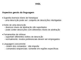
Modeling • Dataflow - concurrent: gate level representation • Structural - concurrent: hierarchically interconnected components • Behavioral - sequential: algorithm level representation
A VHDL design is a set of design entities, one of which is the “top level”, which may invoke other design entities as components.The entire design, is based on the ability to utilize “design hierarchy”.
Entities and Architectures Entity- defines the interface (e.g., inputs/outputs) to a ‘black box’ which performs a specific function. Architecture- one possible implementation (or realization) of the “insides” of the “black box”. • An architecture may contain: • data declarations • concurrent signal assignment • component instantiations • process blocks
Entities Example: entity ALU is port ( arg1, arg2: in bit_vector(3 downto 0); add_or_sub: in bit; result: out bit_vector(3 downto 0); end ALU; “Black Box” Entity -I/O for Box ALU arg1, arg2 result add_or_sub
Architectures Example: architecture ALU_struct of ALU is component add port (arg1,arg2: inbit_vector(3 downto 0); result: outbit_vector(3 downto 0); end component; ... signal diff, sum: bitvec; ... begin diff <= arg1- arg2; add0: add port map(arg1,arg2,sum); … end ALU_struct; Architecture Inside of Box ALU Add Mux Sub
Data Types Supported • bitA: in bit; • bit_vector B: in bit_vector(7 downto 1); • constants ‘1’, or ‘0’, or “10010” • bitvecB: bitvec; • integerC: integer; • realC: real; • std_logicD: std_logic; (IEEE library) • User defined
Concurrent Signal Assignment NOT (single input) a <= not(b); AND (multiple input) a <= b and c; OR (multiple input) a <= b or c or d; XOR (multiple input) a <= (b xor c xor d) xor e;
Concurrent Signal Assignment NAND (multiple input) a <= b nand c; NOR (multiple input) a <= b nor c nor d; Bit-wise Concatenation (“&”) a(6 downto 1) <= c & d(3 downto 0) & e; Selector (multiplexor) c <= b when (en = ‘1’) else a;
ExamplesDataflow and Structural • AND gate • Half Adder • Full Adder • 2 Bit 2 to 1 Multiplexor • 4 Bit Ripple Carry Adder
A Z B AND Gate entity andf is port (A, B: in BIT; Z: out BIT); end andf; architecture andf of andf is begin Z <= (A and B); end andf; A andf Z B
A SUM B COUT Half Adder entity Half_Adder is port (A, B: in BIT; SUM, COUT: out BIT); end Half_Adder; architecture Half_Adder of Half_Adder is begin SUM <= A xor B after 6ns; COUT <= A and B after 4ns; end Half_Adder; SUM A Half_Adder B COUT
Full Adder CIN entity Full_Adder is port (A, B,CIN: in BIT; SUM, COUT: out BIT); end Half_Adder; architecture Full_Adder of Full_Adder is begin SUM <= A xor B xor CIN after 15ns; COUT <= (A and B) or (B and CIN) or (CIN and A) after 10ns; end Full_Adder; SUM A Full_Adder B COUT SUM CIN A COUT B
S A Mux1 F B 1-Bit 2 to 1 Multiplexor entity Mux1 is port (A, B, S: in bit; F: out bit); end Mux1; architecture mux1 of mux1 is begin F <= A when (S = ‘0’) else B; end Mux1; S A A S=0 F F B B S=1
2-Bit 2 to 1 Multiplexor entity Mux2 is port (A, B: in bit_vector(1 downto 0); S: in bit; F: out bit_vector(1 downto 0)); end Mux2; architecture Mux2 of Mux2 is component Mux1 port(A,B,S: in bit; F: out bit); end component; begin M0: Mux1 port map(A(0), B(0), S, F(0)); M1: Mux1 port map(A(1), B(1), S, F(1)); end Mux2; S Mux2 A<1:0> S A0 M0 F0 B0 F<1:0> S A1 M1 F1 B<1:0> B1
CIN CIN S<3:0> S(0) A(0) Full_Adder A<3:0> B(0) C(0) SUM CIN S(1) B<3:0> A(1) Full_Adder A COUT B(1) C(1) B S(2) A(2) Full_Adder B(2) C(2) S(3) A(3) Full_Adder B(3) COUT COUT
CIN S<3:0> Ripple_Adder A<3:0> B<3:0> COUT 4 Bit Ripple Carry Adder entity Ripple_Adder is port (A, B: in bit_vector(3 downto 0); CIN: in bit; S: out bit_vector(3 downto 0); COUT: out bit); end Ripple_Adder; architecture Ripple_Adder of Ripple_Adder is component Full_Adder port(A,B,CIN: in bit; SUM, COUT: out bit); end component; signalC: bit_vector(2 downto 0); begin FA0: Full_Adder port map(A(0), B(0), CIN, S(0), C(0)); FA1: Full_Adder port map(A(1), B(1), C(0), S(1), C(1)); FA2: Full_Adder port map(A(2), B(2), C(1), S(2), C(2)); FA3: Full_Adder port map(A(3), B(3), C(2), S(3), COUT); end Ripple_Adder;
Designing with VHDL Design Process: (lab 13) 1. Design entry (VHDL) 2. Testing (VHDL test vector simulation) 3. Synthesis (FPGA, standard cell, full custom) 4. Testing (logic analyzer)
Cutting Edge Technology • FPGA (can be found in many systems) • VHDL (1998 DoD requires all ASIC suppliers to deliver VHDL description of the ASIC and their sub components at both the behavioral level and structural level) • Put FPGA and VHDL in your resume!
Behavioral VHDL • Built from “process” blocks • Each block is sequential internally • Can use variables • Can use conditionals, loops, etc. • Can maintain state • The complete process is like a “big gate” • Like gates, blocks operate concurrently
Example: SR Flip-FlopDataflow Implementation entity sr_df is port( s, r in bit; q, qbar out bit); end sr_df; architecture sr_df of sr_df is signal p, pbar bit; begin p <= not(s) nand pbar after 1 ns; pbar <= not(r) nand p after 2 ns; q <= p; qbar <= pbar; end sr_df;
Example: SR Flip-FlopBehavioral Implementation entity sr_bhv is port( s, r in bit; q, qbar out bit); end sr_bhv; architecture sr_bhv of sr_bhv is begin flipflop : process (s,r) variable test bit; begin test := s OR r; if (test = '1') then q <= s; qbar <= r; end if; endprocess flipflop; end sr_bhv;
Traffic Light Controller Side Road Car Sensor Main Road Main Road Car Sensor Side Road
State Machine Design • Inputs, Outputs, States, Transitions Main Go Main_car = 0 • For each state • How do the inputs affect the state transition? • What outputs are set? Main_car = 1 All Stop Side_car = 0 Side Go Side_car = 1
Traffic Light Controller -- Library Clause (picks a default search library) LIBRARY ieee; -- Use Clause (picks sets of definitions from libraries) USE ieee.std_logic_1164.all; -- Entity Declaration ENTITY test1 is port (clk, Side_Car, Main_Car: IN STD_LOGIC; Main_Green, Main_red, Side_Green, Side_red: OUT STD_LOGIC); END test1;
-- Architecture Body ARCHITECTURE test1 OF test1 IS TYPE STATE_TYPE IS (All_Stop, Main_Go, Side_Go); SIGNAL state: STATE_TYPE; BEGIN PROCESS (clk) BEGIN IF clk'EVENT AND clk = '1' THEN -- rising edge CASE state IS WHEN All_Stop => IF (Main_Car = '1') THEN state <= Main_Go; ELSIF (Side_Car = '1') THEN state <= Side_Go; END IF;
-- State Transitions con’t WHEN Side_Go => IF not(Side_Car = '1') THEN state <= All_Stop; END IF; WHEN Main_Go => IF not(Main_Car = '1') THEN state <= All_Stop; END IF; END CASE; END IF; END PROCESS;
-- Output Assignments WITH state SELECT Main_Green <= '1' when Main_Go, '0' when Side_Go, '0' when All_Stop; WITH state SELECT Side_Green <= '1' when Side_Go, '0' when Main_Go, '0' when All_Stop; WITH state SELECT Main_Red <= '1' when All_Stop, '1' when Side_Go, '0' when Main_Go; WITH state SELECT Side_Red <= '1' when All_Stop, '0' when Side_Go, '1' when Main_Go; END test1;
Multiplicand Multiplier Partial Product Partial Product Partial Product Partial Product Product Multiplier Shifted Copies of Multiplicand X
Multiplicand Product Product Product Multiplier If (Multiplier( i ) = 1) + Shifted Copies of Multiplicand + Partial Products
ENTITY mpy IS PORT (op1, op2 : IN STD_LOGIC_VECTOR(3 DOWNTO 0); result : OUT STD_LOGIC_VECTOR(7 DOWNTO 0); clk: in STD_LOGIC); END mpy; ARCHITECTURE test OF mpy IS -- shift and add technique BEGIN Fred: PROCESS(clk) VARIABLE multiplier : STD_LOGIC_VECTOR(3 DOWNTO 0); VARIABLE multiplicand : STD_LOGIC_VECTOR(7 DOWNTO 0); VARIABLE product : STD_LOGIC_VECTOR(7 DOWNTO 0) := "00000000"; VARIABLE i : integer; BEGIN IF clk'EVENT AND clk = '1' THEN multiplier := op1; multiplicand := "0000" & op2; product := “00000000”; FOR i IN 3 DOWNTO 0 LOOP product(7 downto 0) := product(6 downto 0) & "0"; IF (multiplier(i) = '1') THEN product := product + multiplicand; END IF; END LOOP; result <= product; END PROCESS; END IF; END TEST;