BCAL Construction and Readout Update: SiPM Contributions and Progress Overview
This document provides a comprehensive update on the BCAL construction and readout activities, highlighting the contributions of SiPMs from various collaborators. It covers aspects such as construction logistics, module assembly, project coordination, and training for construction crews. The update also discusses performance metrics, alternative readout configurations, and ongoing simulations addressing issues like light guides and geometry. Key performance specifications and targets related to SiPM tests and device details are outlined, along with a roadmap reflecting current progress and schedule adjustments.

BCAL Construction and Readout Update: SiPM Contributions and Progress Overview
E N D
Presentation Transcript
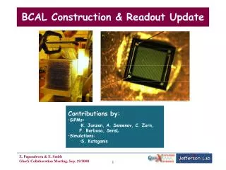
BCAL Construction & Readout Update • Contributions by: • SiPMs: • K. Janzen, A. Semenov, C. Zorn, F. Barbosa, SensL • Simulations: • S. Katsganis 1
Overview • BCAL Construction • Start in Spring ‘09? • SiPM Progress • JLab, Regina, SensL: meetings, reports • Performance: PDE, DR, array assembly • Alternative Readout • Simulation Issues 2
Construction Logistics • Total calendar days for delivery of 49 modules: 817 days from D-0. • Project Coordination • Base Crew: undergraduates • Construction Manager: one person, full time over the entire construction period; will be trained in construction techniques and will be responsible for day-to-day supervision and QA of the matrix build, as well as crew contacting and scheduling, and reporting. Draft ad exists. • Training: Regina faculty and staff will do the initial training of the construction crew and the Construction Manger (CM). From then on, the CM will take over this task for the subsequent crews with assistance from Regina, during carefully timed trips of the latter to Edmonton. • Chief Machinist: Gilbert Lachat (UofA/CPP) • Supervising Engineer: Jan Soukup (UofA/CPP) • Oct. 15 visit to U of Alberta: Elke, Elton, Tim, George, Zisis 5
BCAL Readout Considerations • Technical specifications: outlined in GlueX-doc-795-v17 • SiPM tests are underway; past/ recent results of tests of fine mesh PMTs • Geometry: especially related to acceptance gap between BCAL and FCAL • Light guides and inactive material is different for the two options. We need to simulate the effect of each • Precise configuration of light guides for FM PMTs on the upstream end, where the field at the end of the BCAL exceeds 0.5 T • Detail description of cables and electronics on each detector • Granularity: optimization of distribution between inner and outer detectors • Which detectors should have discriminators and TDCs • Study of signal splitting, choice of discriminator; this has an impact on no of cables • Resolution: Complete simulation studies for correct thresholds for the FM • Studies of timing resolution. Realistic simulation for both photons & charged particles • Resolution for various geometry options (mentioned above) 6
Roadmap • SensL is not meeting our PDEDR requirement • Schedule delay: 3-4 months • Contract extended • Sept 22 decision for array cell type Contract Start 7
Targets & Device Details (GlueX-doc-795-v17) • Devices: • SPMMicro • SPMArray • SPMPlus • Processes: • Trenching • Gettering • Electronics SPMMicro Test Samples @JLab (+ 2 @Regina) No trenching • A20HD (3 samples) - 1 mm^2 - (circular pi/4 mm^2 area)- Getter 2 - 848 microcells - FF = 43% • A35HD (3 samples) - 1 mm^2 (circular) - Getter 2 - 400microcells - FF = 59% • A20HD (3 samples) - 3x3 mm^2 (square 2.85 x 2.85 mm^2)- Getter 1 - 8640 microcells - FF = 43% • A35HD (3 samples) - 3x3 mm^2 (square) - Getter 2 - 3640 microcells - FF = 59% • A35HD (3 samples - 1 defective) - 3x3 mm^2 (square) - Getter 1- 3640 microcells - FF = 59% 8
Gettering - PDE/DR effect(SensL, C. Zorn) • Gettering process drives DC reduction • Weaker effect on edge intensive device (20um) • Minimal DC reduction going from Getter #1 to Getter #2 processing for A20H device. • PDE reduction significant with the introduction of Gettering (more than originally anticipated). • Closet Device to specifications: • A35H Getter #1 process: 13.5% PDE and 8MHz DC per SPM. (No Getter) (Getter #1) (No Getter) (Getter #2) (Getter #1) (Getter #2) 9
Specification: PDE vs Dark Rate (GlueX-doc-795-v17) Design Goal (fixed resolution) (0.12, 42) 20% sampfrac 13/16 Scaled by x16 10
Electronics and Timing • SPMPlus TIA Boards, labeled 080723 #2 and #3. • Frequency response, transient simulation, pulse response • Optimization of the rise time and gain possible once final sensors are available and input capacitance is fully characterized. • SPMPlus electronics boards are well behaved and exhibit very low output offset voltage. no abnormalities in tail (GlueX-doc-1024) 11 ns rise time -200 V offset • Baseline shift • Noise at different frequencies • 2nd pulse 11
SPMMicro: Performance May + 20 C Sept 12
SPMMicro: DR & Cross Talk Extrapolated x16 Sept May Correct by 13/16 13
SPMMicro: 90Sr (GlueX-doc-1066) • Devices tested: • 1-mm2 A20HD/A35HD, 9-mm2 A20HD • IV scans: Vbr origin slight diffs • 90Sr source + green fiber tests: • good rise and fall times; • level shift, no second pulse, lots of noise in the analog pulses, pedestal resolution from SPM • Results: • Nice p.e. peaks at diff overbias • Good linearity; p.e. lines intercept at +0.85 V • Good linearity also on plot versus no. of p.e. for different overbias curves 14
SPMPlus: Assembly Issues (GlueX-doc-1024) • Setup: laser, fiber, SMA connector, green fiber, 1mm collimator, x-y stage, scope • Laser at 2.5MHz, 60ps pulse • Over-bias: +2V (at 28.3 V) • 10 ns rise, 70 ns decay • Uniformity improved (8 cells within 10%, 12 within 20%) Pixel Failures • Type 1: Low Gain Output /Good Timing • This pixel behaviour results in as much as 2x reduction in optical output over normal pixels. • Problem corrected by optical binning procedure. • Type 2: Dead Channels • 50% yield on early assemblies based on electrical IV measurements. • Root cause was with subcontractor process where poor metal adhesion was identified due to insufficient adhesion layer resulting in delamination of the metal from the glass. • Latest builds (Build ID: 080408_1_10) have shown 100% yields on a batch of 10 array builds (i.e. all 160 channels fully functional). No type 2 defect observed indicating that new adhesion process has fixed the fail mode. Wafer Selection 15
SPMPlus: No. of p.e. - summary (GlueX-doc-1069 and 1066) (see Beni’s talk (doc-1106) for new results - 90Sr+fiber) 16
Thinner Lead Sheets? Rear+sides candidate? • Objectives • increase sampling fraction • lower threshold and relax demand on PDE • GEANT3 simulations with new geometry; they agree with FLUKA 2006.3b nominal 0.26mm 0.5mm Pb 1.0mm Pb Clad Glue KLOE samples 0.20mm 0.2mm Pb candidate? nominal Glue 0.2mm Pb 0.20mm 17
In a nutshell… • A20HD SPMMicro has yielded PDE of ~6%- 9% in the +1.5V to +3V range, consistent with SensL’s numbers • A35HD 3x3mm2 extrapolated/measured ~12-13%, DR ~ 80-90 MHz • SPMPlus: no. of p.e. consistent with PMTs with blue and green fibers • Significant improvement in Si wafer selection: optical binning • Significant array manufacturing improvement: no delamination • Progress is promising, but we need SPMMicro A35H PDE >12% and DR<40MHz, plus fully functioning SPMPlus arrays • Upcoming decision: base cell for SPMPlus arrays • But, we are not out of the woods…so, look at Plan B 18
BCAL Alternative Readout Comparison standard and alternative readout alternative readout based on fine mesh Hamamatsu PMTs: New segmentation: inner (2 x (3x3) channel) 1” FM-PMT outer remains (2 x (2x2) channel) 1.5” FM-PMT performance operate in magnetic field up to 0.5 Tesla • upstream B-field > 0.5T • increase light guide from • 10 cm to 55 cm • Disadvantage: • Cost increase by ~350k$ (Courtesy of Elke) 19
Simulation studies needed (see Blake’s talk (doc-1101) for newest results) • Resolution comparison: 6x4 vs 3x3 segmentation • Improved simulation of resolutions • Include realistic threshold for FM option • Studies of timing resolution • Study impact of inactive material at the end of BCAL on acceptance • Inactive material includes light guides, light detector, cables, dark box or cover, etc. • Comparison between SiPM and FM options • How many (which) changes in geometry should be studied? 23
Carl’s Setups PDE Getter N 25
SPMMicro: A35HD vs A20HD 1mm2 • PDE under identical geometries and illumination conditions: • PDE1mmA35HD/PDE1mmA20HD=1.35 projected Solid angle effect • A20HD 9mm2 measurements are robust; extrapolate to A35HD 9mm2 PDE. • A35HD has better resolution. PDE9mmA35HD=1.35*PDE9mmA20HD=~12Carl: ~13% 27
SPMMicro: Laser (Regina June 30 Report) • Kathryn’s details… 28
SPMPlus: No. of p.e. - setup (GlueX-doc-1069) 29
BCAL Readout Possibilities mechanically not possible nominal design alternative design 31