
Overview of Maintenance Options for Next-Generation Fusion Pilot Plants
This document provides a comprehensive overview of the design and maintenance strategies for fusion pilot plants based on various magnetic configurations, including the Advanced Tokamak (AT), Spherical Tokamak (ST), and Compact Stellarator (CS). The study evaluates in-vessel component removal techniques through horizontal and vertical ports, highlighting diagnostic and coolant systems. The report assesses each configuration's ability to meet operational challenges and outlines future research needs to enhance maintenance access and efficiency for commercial fusion energy production.

Overview of Maintenance Options for Next-Generation Fusion Pilot Plants
E N D
Presentation Transcript
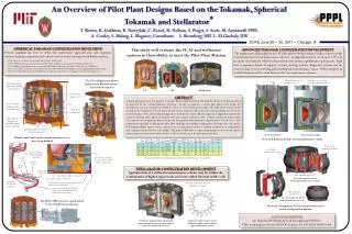
Full in-vessel component removal Outboard blanket removed through vertical port Complete in-vessel assembly removed through horizontal port Horizontal divertor access In-vessel components removed through vertical ports An Overview of Pilot Plant Designs Based on the Tokamak, Spherical Tokamak and Stellarator*T. Brown, R. Goldston, R. Hawryluk, C. Kessel, H. Neilson, S. Prager, S. Scott, M. Zarnstorff; PPPL A. Costley, S. Malang, L. Waganer; Consultants L. Bromberg; MIT L. EI-Guebaly; UW One segments per TF coil ST AT Stellarator In-vessel segments for the horizontal maintenance scheme SOFE June 26 – 30, 2011 – Chicago, Ill SPHERICAL TOKAMAK CONFIGURATION DEVELMENT Present emphasis has been to define the maintenance approach plus add diagnostic systems, heating components and critical services to the Centerpost and Blanket system,. Stellarator segmentation can be defined at higher aspect ratio to gain maintenance access ADVANCED TOKAMAK CONFIGURATION DEVELOPMENT The maintenance philosophy for the AT pilot plant is being evaluated with a renewed study of horizontal and vertical maintenance schemes. Configurations based on 16 and 12 TF coils are under development with PF coils positioned for plasma equilibrium requirements. High level component details of support systems, heating systems, diagnostic systems and in-vessel coolant services are being added to help assess maintenance issues. When complete an overall evaluation will be made between the two maintenance schemes. Stellarator segmentation scheme that uses removable internal saddle coils to provide maintenance access This study will evaluate the ST, AT and stellarator options in their ability to meet the Pilot Plant Mission Three segments per TF coil The NB ports are sized to accommodate the JT60-SA NNBI system. Nine NNBI injector ports are placed in a pinwheel shape with port center tangent to the plasma at R0-a/2. One midplane radial diagnostic port is provided with additional ports possible above (and below) the NNBI ports. In-vessel coolant services have been added to the inboard VV/FW and to the Blanket systems supplying PbLi and He cooling. The lower outboard vacuum seal configuration was altered to improve the seal engagement and weld/cutting access. Vertical Assembly Horizontal Assembly In-vessel segments for the vertical maintenance scheme The ST configuration allows independent Blanket system / Centerstack removal External structure supporting a sliding joint TF system VV located inside the TF ABSTRACT A fusion pilot plant study was initiated to evaluate the potential benefits of following the fission development path as an approach for the commercialization of fusion. In such an approach, a fusion pilot plant would bridge the development needs in moving from ITER to a first of a kind fusion power plant. The pilot plant mission would encompass the component test and fusion nuclear science missions while at the same time producing net electricity. In the first phase of the study scoping designs were developed for three different magnetic configuration options: the advanced tokamak (AT), spherical tokamak (ST) and compact stellarator (CS). Critical component features have been added to the designs that impact the general arrangement and maintenance characteristics of each device. The requirements specified in defining the pilot plant challenge the machine configurations developed for each option. Developing multiple options with a consistent set of requirements enables a uniform comparison of configuration and component issues that drive each design. This paper will provide an engineering design overview of each option, address open issues and assess where further work is needed to meet the pilot plant objectives. S/C external PF coils housed in a vacuum enclosure 25.2 m Felt metal sliding joint Copper divertor shaping coils embedded within the TF centerstack 22.3 m Opening expanded to improve felt metal joint access Blanket and Centerstack coolant system services have been defined Renewed horizontal and vertical maintenance study Inboard VV/FW/Div return and supply coolant lines Pair of 609 mm OD outer concentric pipes for PbLi and He coolant system Parameters for AT, ST, and CS pilot plants for thermal efficiency nth = 0.3 and 0.45. FW/VV inlet Lower div inlet Lower div outlet STELLARATOR CONFIGURATION DEVELOPMENT Optimization of a stellarator maintenance scheme may lie within the combination of higher aspect ratio and some added internal saddle coils Welder/Cutter pip access Outer divertor supply - 140 mm OD Inner divertor supply - 197 mm OD Centerstack VV/FW/Div components Outboard divertor system coolant supply/return manifolds located inside the VV Inboard divertor/FW system coolant supply/return manifold located just outside of the TF vertical leg The JT60 NNBI system is a good match to the ST physics parameters In-vessel arrangement for horizontal and vertical access configuration options ACKNOWLEDGEMENTS: Dr. Hanada JT60 NBI group head for supplying NNBI files *This work supported by the US DOE Contract No. DE-AC02-09CH11466


