PROGRAMMABLE LOGIC CONTROLLERS
PROGRAMMABLE LOGIC CONTROLLERS. Richard A. Wysk IE450 - Manufacturing Systems. PURPOSE OF Programmable Logic Controllers (PLCs). Initially designed to replace relay logic boards Sequence device actuation Coordinate activities

PROGRAMMABLE LOGIC CONTROLLERS
E N D
Presentation Transcript
PROGRAMMABLELOGIC CONTROLLERS Richard A. Wysk IE450 - Manufacturing Systems
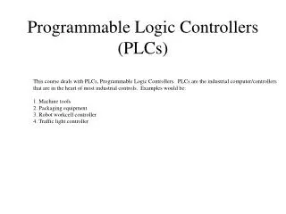
PURPOSE OF Programmable Logic Controllers (PLCs) • Initially designed to replace relay logic boards • Sequence device actuation • Coordinate activities • Accepts input from a series of switches • Sends output to devices or relays
FUNCTIONS OF CONTROLLERS • 1) on-off control, • 2) sequential control, • 3) feedback control, and • 4) motion control.
CONTROL DEVICES 1) mechanical control - cam, governor, etc., 2) pneumatic control - compressed air, valves, etc. 3) electromechanical control - switches, relays, a timer, counters, etc, 4) electronics control - similar to electromechanical control, except uses electronic switches. 5) computer control.
PROGRAMMABLE LOGIC CONTROLLER "A digitally operating electronic apparatus which uses a programmable memory for the internal storage of instructions by implementing specific functions such as logic sequencing, timing, counting, and arithmetic to control, through digital or analog input/output modules, various types of machines or processes. The digital computer which is used to perform the functions of a programmable controller is considered to be within this scope. Excluded are drum and other similar mechanical sequencing controllers." Invented in 1968 as a substitute for hardwired relay panels. National Electrical Manufacturing Association (NEMA)
VENDORS Rockwell GE/Fanuc Schnieder etc.
PLC Input CPU Input Module Flag System Output Module Output User Ladder Diagram Working memory registers
What devices does a PLC interact with? • INPUT RELAYS-(contacts)These are connected to the outside world. They physically exist and receive signals from switches, sensors, etc. Typically they are not relays but rather they are transistors. • INTERNAL UTILITY RELAYS-(contacts) These do not receive signals from the outside world nor do they physically exist. They are simulated relays and are what enables a PLC to eliminate external relays. There are also some special relays that are dedicated to performing only one task. Some are always on while some are always off. Some are on only once during power-on and are typically used for initializing data that was stored. • COUNTERS-These again do not physically exist. They are simulated counters and they can be programmed to count pulses. Typically these counters can count up, down or both up and down. Since they are simulated they are limited in their counting speed. Some manufacturers also include high-speed counters that are hardware based. We can think of these as physically existing. Most times these counters can count up, down or up and down.
What devices does a PLC interact with?Continued • TIMERS-These also do not physically exist. They come in many varieties and increments. The most common type is an on-delay type. Others include off-delay and both retentive and non-retentive types. Increments vary from 1ms through 1s. • OUTPUT RELAYS-(coils)These are connected to the outside world. They physically exist and send on/off signals to solenoids, lights, etc. They can be transistors, relays, or triacs depending upon the model chosen. • DATA STORAGE-Typically there are registers assigned to simply store data. They are usually used as temporary storage for math or data manipulation. They can also typically be used to store data when power is removed from the PLC. Upon power-up they will still have the same contents as before power was removed. Very convenient and necessary!!
SWITCHES DPST SPDT
TERMS Throw - number of states Pole - number of connecting moving parts (number of individual circuits). SPDT A serial switch box (A-B box) has two 25 pin serial ports to switch from. A B Output Input DPST Knob How is this switch classified?
TYPES OF SWITCHES 1. Basic switch, operated by a mechanical level, 2. Push-button switch, 3. Slide switch, 4. Thumbwheel switch, 5. Limit switch, 6. Proximity switch, and 7. Photoelectric switch. RATING: voltage, current
RELAYS A switch whose operation is activated by an electromagnet is called a "relay" Relay coil Output contact
COUNTER Digital counters output in the form of a relay contact when a preassigned count value is reached. 5
TIMER A timer consists of an internal clock, a count value register, and an accumulator. It is used for or some timing purpose. Time 5 seconds.
AN EXAMPLE OF RELAY LOGIC For process control, it is desired to have the process start (by turning on a motor) five seconds after a part touches a limit switch. The process is terminated automatically when the finished part touches a second limit switch. An emergency switch will stop the process any time when it is pushed.
PLC ARCHITECTURE Programmable controllers replace most of the relay panel wiring by software programming. A typical PLC
PLC COMPONENTS 1. Processor Microprocessor based, may allow arithmetic operations, logic operators, block memory moves, computer interface, local area network, functions, etc. 2. Memory Measured in words. ROM (Read Only Memory), RAM (Random Access Memory), PROM (Programmable Read Only Memory), EEPROM (Electronically Erasable Programmable ROM), EPROM (Erasable Programmable Read Only Memory), EAPROM (Electronically Alterable Programmable Read Only Memory), and Bubble Memory.
PLC COMPONENTS 3. I/O Modular plug-in periphery AC voltage input and output, DC voltage input and output, Low level analog input, High level analog input and output, Special purpose modules, e.g.., high speed timers, Stepping motor controllers, etc. PID, Motion 4. Power supply AC power 5. Peripheral Hand held programmer (loader), CRT programmer, Operator console, Printer, Simulator, EPROM loader, Cassette loader, Graphics processor, and Network communication interface. MAP, LAN
LADDER DIAGRAM A ladder diagram (also called contact symbology) is a means of graphically representing the logic required in a relay logic system. Rail Rung
PLC WIRING DIAGRAM External switches Stored program
SCAN A PLC resolves the logic of a ladder diagram (program) rung by rung, from the top to the bottom. Usually, all the outputs are updated based on the status of the internal registers. Then the input states are checked and the corresponding input registers are updated. Only after the I/Os have been resolved, is the program then executed. This process is run in a endless cycle. The time it takes to finish one cycle is called the scan time. Output Input begin Idle Scan cycle Resolve logic
PLC INSTRUCTIONS 1) Relay, 2) Timer and counter, 3) Program control, 4) Arithmetic, 5) Data manipulation, 6) Data transfer, and 7) Others, such as sequencers.
LOGIC STATES ON : TRUE, contact closure, energize, etc. OFF: FALSE, contact open , de-energize, etc. Do not confuse the internal relay and program with the external switch and relay. Internal symbols are used for programming. External devices provide actual interface. (In the notes we use the symbol "~" to represent negation. AND and OR are logic operators. )
AND and OR LOGIC AND OR
COMBINED AND & OR R1 = PB1 .OR. (PB2 .AND. PB3) pb3
RELAY A Relay consists of two parts, the coil and the contact(s). Contacts: a. Normally open -| |- b. Normally closed -|/|- c. Off-on transitional -||- d. On-off transitional -| |- Coil: a. Energize Coil -( )- b. De-energize -(/)- c. Latch -(L)- d. Unlatch -(U)- ( )
TIMERS AND COUNTERS Input True False True Timers: a. Retentive on delay -(RTO)- b. Retentive off delay -(RTF)- c. Reset -(RST)- Counter: a. Counter up -(CTU)- b. Counter down -(CTD)- c. Counter reset -(CTR)- RTO counting stop counting resume RTF stop counting stop RTO reach PR value, output ON RTF reach PR value, output OFF PR value in 0.1 second
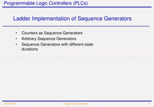
SEQUENCER Sequencers are used with machines or processes involving repeating operating cycles which can be segmented into steps. Output Step A B C Dwell time 1 ON OFF OFF 5 sec. 2 ON ON OFF 10 sec. 3 OFF OFF ON 3 sec. 4 OFF ON OFF 9 sec.
A-B PLC I/O points are numbered, they correspond to the I/O slot on the PLC. For A-B controller used in our lab I/O uses 1-32 Internal relays use 033 - 098 Internal timers/counters/sequencers use 901-932 Status 951-982
PROGRAMMING EXAMPLE 1 id description state explanation MSI microswitch 1 part arrive R1 output to bar code reader 1 scan the part C1 input from bar code reader 1 right part R2 output robot 1 loading cycle R3 output robot 1 unloading cycle C2 input from robot 1 robot busy R4 output to stopper 1 stopper up C3 input from machine 1 machine busy C4 input from machine 1 task complete
SOLUTION Rung 1. If part arrives and no part is stopped, trigger the bar code reader. Rung 2. If it is a right part, activate the stopper. Rung 3. If the stopper is up, the machine is not busy and the robot is not busy, load the part onto the machine. Rung 4. If the task is completed and the robot is not busy, unload the machine.
EXAMPLE 2 TRAFFIC LIGHTS Main street Cycle time Street Red Yellow Green Main 3 1 4 Jefferson 5 1 2 Jefferson street