Download

1 / 32
320 likes | 342 Vues
Understand the intricacies of injection molding processes, learn about the most common defects and their remedies, including flow lines, sink marks, and vacuum voids in plastic molding. Improve your knowledge and techniques for successful plastic manufacturing.

E N D
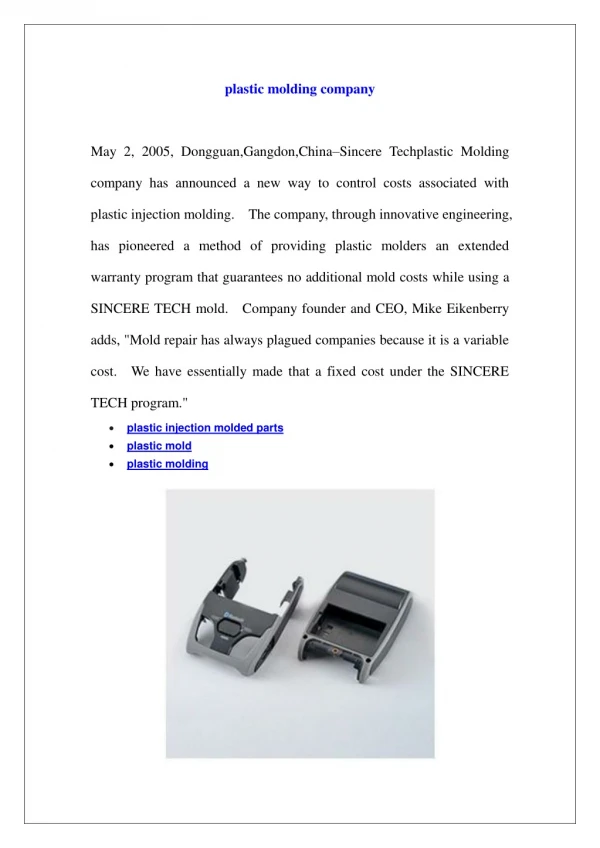
Global Procurement - Supplier QualityPlastic molding Lise Robert SQS (Supplier Quality Specialist) Rev. 01 – Nov 29th 2018
Plastics processes Injection molding Compression Molding Calendering Extrusion Blow molding Line Bending Vacuum Forming Rotational Molding
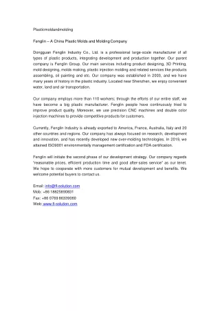
Injection Molding • Injection molding machines have many components and are available in different configurations, including a horizontal configuration and a vertical configuration. However, regardless of their design, all injection molding machines utilize a power source, injection unit, mold assembly, and clamping unit to perform the four stages of the process cycle • Injection moulding is a highly automated production process for producing large quantities of identical items. Granulated or powdered thermoplastic material is heated, melted and then forced under pressure into a mould. Once in the mould the material cools, forming a component that takes on the shape of the mould cavity.
Injection moulding Horizontal molding machine Process • Plastic powder or granules are fed from a hopper into a hollow steel barrel which usually contains a rotating screw. • The barrel is surrounded by a jacket of heaters which melt the plastic material as it is carried along the barrel by the screw towards the mould. This part of the process is similar to the heating and compacting stages in the extrusion process. The screw is forced back as the melted plastic collects at the end of the barrel. Once a sufficient charge of melted plastic has accumulated a hydraulic ram forces the screw forward injecting the thermoplastic through a sprue into the mould cavity. The diagram (left) shows a typical injection moulding machine. This one is capable of exerting forces of up to 250 tonnes. Pressure is kept on the mould until the plastic has cooled sufficiently for the mould to be opened and the component ejected. Vertical molding machine
11 mostcommondefects • Flow Lines • Sink Marks • Vacuum Voids • Surface Delamination • Weld Lines • Short Shots • Warping • Burn Marks • Jetting • Flash • Splay
Flow Line • Causes:Flow line defects are caused by the varying speed at which the molten plastic flows as it changes direction through the contours and bends inside the mold tool. They also occur when the plastic flows through sections with varying wall thickness, or when the injection speed is too low causing the plastic to solidify at different speeds. • Remedies:Increase injection speeds and pressure to the optimal level, which will ensure the cavities are filled properly (while not allowing the molten plastic time to start cooling in the wrong spot). The temperature of the molten plastic or the mold itself can also be elevated to ensure the plastic does not cool down sufficiently to cause the defect. • Round corners and locations where the wall thickness changes to avoid sudden changes in direction and flow rate. • Locate the gate at a spot in the tool cavity with thin walls. Description: Flow lines are streaks, patterns, or lines - commonly off-toned in color - that show up on the prototype part as a consequence of the physical path and cooling profile of the molten plastic as it flows into the injection mold tooling cavity. Injection molded plastic begins its journey through the part tooling via an entry section called a “gate.” It then flows through the tool cavity and cools (eventually hardening into a solid).
Sink Marks • Causes: Sink marks are often caused when the cooling time or the cooling mechanism is insufficient for the plastic to fully cool and cure while in the mold. They can also be caused by inadequate pressure in the cavity, or by an excessive temperature at the gate. All else being equal, thick sections of the injection molded part take longer to cool than thin ones and so are more likely to be where sink marks are located. • Remedies:Mold temperatures should be lowered, holding pressure increased, and holding time prolonged to allow for more adequate cooling and curing. • Reducing the thickness of the thickest wall sections will also ensure faster cooling and help reduce the likelihood of sink marks. Description: Sink marks are small craters or depressions that develop in thicker areas of the injection molded prototype when shrinkage occurs in the inner portions of the finished product. The effect is somewhat similar to sinkholes in topography, but caused by shrinkage rather than erosion.
Bubbles, Vacuum Voids • Causes:Vacuum voids are often caused by uneven solidification between the surface and the inner sections of the part. This can be aggravated when the holding pressure is insufficient to condense the molten plastic in the mold (and thereby force out air that would otherwise get trapped). Voids can also develop from a part that is cast from a mold with two halves that are not correctly aligned. • Remedies: • Locate the gate at the thickest part of the molding. • Reduce melt temperature • Reduce mold temperature • Reduce injection speed • Increase pack and hold pressures • Increase pack and hold times • Dry material to suggested moisture levels • Increase back pressure • Reduce melt temperature • Ensure that mold parts are perfectly aligned. Voids Description: Vacuum voids are pockets of air trapped within or close to the surface of an injection molded part. Bubbles Description: When moisture and/or a gaseous byproduct gets mixed with the melt and is injected in the mold cavity this moisture or gas if embedded inside the melt can show up as bubbles
Surface Delamination • Causes: Foreign materials that find their way into the molten plastic separate from the finished product because the contaminant and the plastic cannot bond. The fact that they cannot bond not only has an affect on the appearance of the prototype, but also on its strength. The contaminant acts as a localized fault trapped within the plastic. An over-dependence on mold release agents can also cause delamination. • Remedies: • Pre-dry the plastic properly before molding. • Increase the mold temperature. • Smooth out the corners and sharp turns in the mold design to avoid sudden changes in melt flow. • Focus more on the ejection mechanism in the mold design to reduce or eliminate the dependence on mold release agents. Description: Surface delamination is a condition where thin surface layers appear on the part due to a contaminant material. These layers appear like coatings and can usually be peeled off (i.e. “delaminate”).
Weld Lines • Causes: Weld lines are caused by the inadequate bonding of two or more flow fronts when there is partial solidification of the molten plastic. • Remedies: • Raise the temperature of the mold or molten plastic. • Increase the injection speed. • Adjust the design for the flow pattern to be a single source flow. • Switch to a less viscous plastic or one with a lower melting temperature Description: A weld or meld line is a weakness or visible flaw created when two or more flow paths meet during the filling process. Weld lines can be caused by material flowing around holes or inserts in the part, multiple injection gates or variable wall thickness where hesitation or "race tracking" can occur. If the different flow fronts have cooled before meeting, they don't interfuse well and can cause a weakness in the molded part. A line, notch and/or color change can appear.
Short Shot • Causes:Short shots can be caused by a number of things. Incorrect calibration of the shot or plasticizing capacities can result in the plastic material being inadequate to fill the cavities. If the plastic is too viscous, it may solidify before fully occupying all the cavities and result in a short shot. Inadequate degassing or gas venting techniques can also result in short shots because air is trapped and has no way to escape; plastic material cannot occupy the space that air or gas is already occupying. • Remedies: • Select a less viscous plastic with higher flowability. This plastic will fill the hardest-to-reach cavities. • Increase mold or melt temperature so as to increase flowability. • Account for gas generation by designing the mold so that gas is not trapped within the mold and is properly vented. • Increase the material feed in the molding machine or switch to a machine that has a higher material feed in the event that the maximum material feed has been reached. Description: As the term implies, short shots can be described as a situation where a molding shot falls short. This means that the molten plastic for some reason does not fully occupy the mold cavity or cavities, resulting in a portion where there is no plastic. The finished product becomes deficient because it is incomplete.
Warping • Causes:Warping is usually caused by non-uniform cooling of the mold material. Different cooling rates in different parts of the mold cause the plastic to cool differently and thus create internal stresses. These stresses, when released, lead to warping. • Remedies: • Ensure that the cooling time is sufficiently long and that it is slow enough to avoid the development of residual stresses being locked into the part. • Design the mold with uniform wall thickness and so that the plastic flows in a single direction. • Select plastic materials that are less likely to shrink and deform. Semi-crystalline materials are generally more prone to warping. Description: Warping (or warpage) is the deformation that occurs when there is uneven shrinkage in the different parts of the molded component. The result is a twisted, uneven, or bent shape where one was not intended.
Burn Marks • Causes:Burn marks are caused either by the degradation of the plastic material due to excessive heating or by injection speeds that are too fast. Burn marks can also be caused by the overheating of trapped air, which etches the surface of the molded part. • Remedies: • Reduce injection speeds. • Optimize gas venting and degassing. • Reduce mold and melt temperatures. Description: Burn marks are discolorations, usually rust colored, that appear on the surface of the injection molded prototypes.
Jetting • Causes: Jetting occurs mostly when the melt temperature is too low and the viscosity of the molten plastic becomes too high, thereby increasing the resistance of its flow through the mold. When the plastic comes in contact with the mold walls, it is rapidly cooled and the viscosity is increased. The material that flows through behind that viscous plastic pushes the viscous plastic further, leaving scrape marks on the surface of the finished product • Remedies: • Increase mold and melt temperatures. • Increase the size of the gate so that the injection speed becomes slower. • Optimize gate design to ensure adequate contact between the molten plastic and the mold. • Change gate location Description: Jetting refers to a situation where molten plastic fails to stick to the mold surface due to the speed of injection. Being fluid, the molten plastic solidifies in a state that shows the wavy folds of the jet stream on the surface of the injection molded part.
Flash • Causes:Flash can occur when the mold is not clamped together with enough force (a force strong enough to withstand the opposing forces generated by the molten plastic flowing through the mold), which allows the plastic to seep through. The use of molds that have exceeded their lifespan will be worn out and contribute to the possibility of flash. Additionally, excessive injection pressure may force the plastic out through the route of least resistance. • Remedies: • Increase the clamp pressure to ensure that the mold parts remain shut during shots. • Ensure that the mold is properly maintained and cleaned (or replaced when it has reached the end of its useful lifespan). • Adopt optimal molding conditions like injection speed, injection pressure, mold temperature, and proper gas venting. Description: Flash is a molding defect that occurs when some molten plastic escapes from the mold cavity. Typical routes for escape are through the parting line or ejector pin locations. This extrusion cools and remains attached to the finished product.
Splay • Dry plastic to suggested moisture levels • Decrease injection speeds • Decrease melt temperature • Decrease screw rotation speeds • Decrease back pressure • Increase mold temperatures • Increase venting • Increase gate sizes Description: A layer/ streak of a unwanted gaseous byproduct from the melt or moisture in the material comes in between the melt flow and the cavity walls preventing the texture from being picked up and in addition eventually leaving a residue
Extrusion • This process can be compared to squeezing toothpaste from a tube. It is a continuous process used to produce both solid and hollow products that have a constant cross-section: for example, a window frame, hose pipe, curtain track, garden trellis. • This extrusion is part of a window seal made from • thermoplastic elastomer (TPE).
Blow moulding Extrusion blow moulding is an automated process that is used extensively to make bottles and other lightweight, hollow parts from thermoplastic materials. • ProcessThe cycle starts with the mould open (1). A hollow length of plastic, called a parison, is extruded down between two halves of the mould (2). • The mould closes and compressed air is blown into the inside of the parison which inflates it, pushing the soft plastic hard against the cold surfaces of the mould (3). The plastic is cooled by the mould, causing it to harden quickly (4). The mould is then opened, the moulding ejected and the waste (called flash) is trimmed off with a knife (5). (4) (5) (3) (1) (2)
Vacuum forming This process is used to manufacture a variety of products in thermoplastic materials. These products range in size from garden-pond liners to food trays used in supermarkets. A typical industrial-size vacuum-forming machine is capable of producing vacuum formings up to 1.8m x 1.5m in size. A mould is attached to a platen (support plate). The platen and mould are then lowered and rigid thermoplastic sheet material is clamped onto an air- tight gasket and usually heated from above. Any trapped air remaining between the platen and the heated plastic sheet is then evacuated by a vacuum pump. Atmospheric pressure acting over the top surface completes the forming process by pressing the plastic sheet onto the mould. Once the plastic sheet has cooled down to below its freeze point the air flow is reversed to lift the forming off the mould. If this is not done quickly the forming tends to grip onto the mould and attempts to prise them apart often result in damage to the forming. Once the thermoplastic sheet is softened enough (i.e. reaches a plastic state) then air is blown in to raise the sheet in a slight bubble before the platen is raised bringing the mould into contact with the plastic.
Compression moulding This is, historically, the oldest commercial plastics moulding process and is mainly used to make products from thermosetting materials. A combination of heat and pressure is used to change the material's form and chemical structure. Materials Typical thermosetting plastics used in compression moulding are urea formaldehyde and phenol formaldehyde. These materials are different from thermoplastics as they cannot be reheated and reshaped because a chemical change, called polymerisation, has taken place. Generally thermosets tend to be harder, stiffer and more resistant to the effects of heat and chemical attack than are thermoplastic materials.
Compression Molding • The raw materials for compression molding are usually in the form of granules, putty-like masses, or preforms. • They are first placed in an open, heated mold cavity. The mold is then closed and pressure is applied to force the material to fill up the cavity. • A hydraulic ram is often utilized to produce sufficient force during the molding process. The heat and pressure are maintained until the plastic material is cured.
Calendering • Plastic film, sheet and coated materials such as wallpaper and fabrics are produced by the calendering process. It involves rolling out a mass of premixed plastics material between large rollers to form a continuous and accurately sized film. • The main material used is PVC; others include ABS and cellulose acetate. PVC ranges from flexible to rigid and the final product is composed of a number of basic materials which must be combined in a uniform mixture of measured ingredients. These ingredients include a resin of a specified molecular weight, stabilisers, lubricants, reinforcing materials, colorants and plasticisers.
Line bending Line or strip bending is used to form straight, small curvature bends in thermoplastic sheet material. The process is quite straightforward. An electric element similar to that in an electric fire, is enclosed in a channel which has an opening at the top. Thermoplastic sheet is placed across supports above the opening. By adjusting the height of these supports the width of strip to be heated can be altered. The supports are set to a low height for tight bends and higher, which has the effect of widening the heated area, if a more gradual bend is required. When using machines which have a single heating element it is necessary to regularly turn over the thermoplastic sheet to ensure both sides of the plastic are heated evenly. This will help to avoid blisters appearing on the surface of the plastic. Heating times will vary according to thickness and colour of the thermoplastic. Bending jigs are used to ensure that each bend is identical on every product.This removes the need to measure and mark out each bend and therefore speeds up the production process.
Rotational moulding Rotational moulding is a process used mainly to manufacture hollow-shaped products such as footballs, road cones and storage tanks up to 3m³ capacity. A measured weight of thermoplastic is placed inside a cold mould like the one below (Station 1). The mould is then closed and moved into an oven chamber (Station 2) where it is heated to a temperature of 230-400°C whilst being rotated simultaneously around both vertical and horizontal axes. Rotational speeds are usually between 2 and 20 r.p.m.