Download
1 / 61
620 likes | 852 Vues
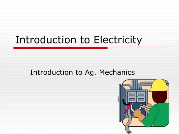
Introduction to Electricity. Charge. Symbol: (q) Unit: Coulomb (C). The fundamental electric quantity is charge. Atoms are composed of charge carrying particles: electrons and protons , and neutral particles, neutrons .

E N D
Charge • Symbol: (q) • Unit: Coulomb (C) • The fundamental electric quantity is charge. • Atoms are composed of charge carrying particles: electrons and protons, and neutral particles, neutrons. • The smallest amount of charge that exists is carried by an electron and a proton. • Charge in an electron: • qe = -1.602x10⁻¹⁹ C • Charge in a proton: • qp = 1.602x10⁻¹⁹ C
Current • Symbol: I • Unit: Ampere • Current moves through a circuit element “through variable.” • Current is rate of flow of negatively-charged particles, called electrons, through a predetermined cross-sectional area in a conductor. • Like water flow. • Essentially, flow of electrons in an electric circuit leads to the establishment of current. • I(t) = • q : relatively charged electrons (C) • Amp = C/sec • Often measured in milliamps, mA
Voltage • Symbol: V • Unit: Volt • Potential difference across two terminals in a circuit “across variable.” • In order to move charge from point A to point B, work needs to be done. • Like potential energy at a water fall. • Let A be the lower potential/voltage terminal • Let B be the higher potential/voltage terminal • Then, voltage across A and B is the cost in energy required to move a unit positive charge from A to B. B A
Series Connection of Cells • Each cell provides 1.5 V • Two cells connected one after another, inseries, provide 3 V, while three cells would provide 4.5 V • Polarities matter
Parallel Connection of Cells • If the cells are connected in parallel, the voltage stays at 1.5 V, but now a larger current can be drawn.
Resistor Concept —I • Flow of electric current through a conductor experiences a certain amount of resistance. • The resistance, expressed in ohms (W, named after George ohm), kilo-ohms (kW, 1000W), or mega-ohms (MW, 106W) is a measure of how much a resistor resists the flow of electricity. • The magnitude of resistance is dictated by electric properties of the material and material geometry. • This behavior of materials is often used to control/limit electric current flow in circuits. • Henceforth, the conductors that exhibit the property of resisting current flow are called resistors. Resistor Symbols
Resistor Concept —II • A resistor is a dissipative element. It converts electrical energy into heat energy. It is analogous to the viscous friction element of mechanical system. • When electrons enter at one end of a resistor, some of the electrons collide with atoms within the resistor. These atoms start vibrating and transfer their energy to neighboring air molecules. In this way, a resistor dissipates electrical energy into heat energy. • Resistors can be thought of as analogous to water carrying pipes. Water is supplied to your home in large pipes, however, the pipes get smaller as the water reaches the final user. The pipe size limits the water flow to what you actually need. • Electricity works in a similar manner, except that wires have so little resistance that they would have to be very very thin to limit the flow of electricity. Such thin wire would be hard to handle and break easily.
Resistor V-I Characteristic • In a typical resistor, a conducting element displays linear voltage-current relationship. (i.e., current through a resistor is directly proportional to the voltage across it). • I µV • Using G as a constant of proportionality, we obtain: • I = GV • Equivalently, • V = RI (or V = IR) • where R = 1/G. • R is termed as the resistance of conductor (ohm, W) • G is termed as the conductance of conductor (mho, )
Resistor Applications • Resistors are used for: • Limiting current in electric circuits. • Lowering voltage levels in electric circuits (using voltage divider). • As current provider. • As a sensor (e.g., photoresistor detects light condition, thermistor detects temperature condition, strain gauge detects load condition, etc.) • In electronic circuits, resistors are used as pull-up and pull-down elements to avoid floating signal levels.
Resistors: Power Rating and Composition • It is very important to be aware of power rating of resistor used in circuits and to make sure that this limit is not violated. A higher power rating resistor can dissipate more energy that a lower power rating resistor. • Resistors can be made of: • Carbon film (decomposition of carbon film on a ceramic core). • Carbon composition (carbon powder and glue-like binder). • Metal oxide (ceramic core coated with metal oxide). • Precision metal film. • High power wire wound.
Resistor Examples Contact leads Symbol for resistor Resistor
Wire-wound resistors have a label indicating resistance and power ratings. A majority of resistors have color bars to indicate their resistance magnitude. There are usually 4 to 6 bands of color on a resistor. As shown in the figure below, the right most color bar indicates the resistor reliability, however, some resistor use this bar to indicate the tolerance. The color bar immediately left to the tolerance bar (C), indicates the multipliers (in tens). To the left of the multiplier bar are the digits, starting from the last digit to the first digit. Resistor value = Resistor Labels
Resistor Color Codes Band color Digit Multiplier Black 0 X1 Brown 1 X10 Color Tolerance Red 2 X100 Brown ±1% Orange 3 X1000 Yellow 4 X10000 Red ±2% Green 5 X100000 Gold ±5% Blue 6 X1000000 Purple 7 X10000000 Silver ±10% Grey 8 X100000000 None ±20% White 9 X1000000000 Silver - x.01 Gold - x.1
Example • The first band is yellow, so the first digit is 4 • The second band is violet, so the second digit is 7 • The third band is red, so the multiplier is • Resistor value is
Metric Units and Conversions Abbreviation Means Multiply unit by Or p pico .000000000001 10 -12 n nano .000000001 10 -9 µ micro .000001 10 -6 m milli .001 10 -3 . Unit 1 10 0 k kilo 1,000 10 3 M mega 1,000,000 10 6 G giga 1,000,000,000 10 9
DigitalMultimeter 1 • DMM is a measuring instrument • An ammeter measures current • A voltmeter measures the potential difference (voltage) between two points • An ohmmeter measures resistance • A multimeter combines these functions, and possibly some additional ones as well, into a single instrument
DigitalMultimeter 2 • Voltmeter • Parallel connection • Ammeter • Series connection • Ohmmeter • Without any power supplied • Adjust range (start from highest limit if you don’t know)
AmmeterConnection • Break the circuit so that the ammeter can be connected in series • All the current flowing in the circuit must pass through the ammeter • An ammeter must have a very LOW input impedance
VoltmeterConnection • The voltmeter is connected in parallel between two points of circuit • A voltmeter should have a very HIGH input impedance
OhmmeterConnection • An ohmmeter does not function with a circuit connected to a power supply • Must take it out of the circuit altogether and test it separately
Resistors in Series Rtotal=R1+R2 Rtotal=1+1=2kΩ
Water in Movable arm Variable Resistor Concept • In electrical circuit, a switch is used to turn the electricity on and off just like a valve is used to turn the water on and off. • There are times when you want some water but don’t need all the water that the pipe can deliver, so you control water flow by adjusting the faucet. • Unfortunately, you can’t adjust the thickness of an already thin wire. • Notice, however, that you can control the water flow by forcing the water through an adjustable length of rocks, as shown to the right.
Terminal B Wiper Terminal A Terminal B Wiper Terminal A Variable Resistor Construction Wiper contact Resistive material Stationary contact • To vary the resistance in an electrical circuit, we use a variable resistor. • This is a normal resistor with an additional arm contact that can move along the resistive material and tap off the desired resistance.
Center pin Symbol for variable resistor Left pin Right pin Variable Resistor Operation • The dial on the variable resistor moves the arm contact and sets the resistance between the left and center pins. The remaining resistance of the part is between the center and right pins. • For example, when the dial is turned fully to the left, there is minimal resistance between the left and center pins (usually 0W) and maximum resistance between the center and right pins. The resistance between the left and right pins will always be the total resistance.
Variable Resistor: Other Examples Thermistor Photoresistor
For a resistor made using a homogenous material • R = • where • r = specific resistance of material (material property) • L = length of conductor used to make the resistor • A = cross-section area of conductor used to make the resistor Resistance Formula
Capacitor Concept • A capacitor is an energy storage element which is analogous to the spring element of mechanical systems. • It can store electrical pressure (voltage) for periods of time. • -When a capacitor has a difference in voltage (electrical pressure) across its plate, it is said to be charged. • -A capacitor is charged by having a one-way current flow through it for a period of time. • -It can be discharged by letting a current flow in the opposite direction out of the capacitor.
+q: positive charge gain due to electrons lost Direction of electron displacement +q: negative charge gained due to electrons gained Capacitor Construction • A capacitor is constructed using a pair of parallel conducting plates separated by an insulating material (dielectric). • When the two plates of a capacitor are connected to a voltage source as shown, charges are displaced from one side of the capacitor to the other side, thereby establishing an electric field. • The charges continue to be displaced in this manner until the potential difference across the two plates is equal to the potential of voltage source.
Pipe filled with water Rubber diaphragm sealing center of pipe Plunger Capacitor Water Pipe Analogy —I • In the water pipe analogy, a capacitor is thought of as a water pipe: • with a rubber diaphragm sealing off each side of the pipe and • a plunger on one end. • When the plunger pushes toward the diaphragm, the water in the pipe forces the diaphragm to stretch until the force of the diaphragm pushing back on the water equals the force on the plungerpipe is charged! • If the plunger is released, the diaphragm will push the plunger back to its original position pipe is discharged.
Capacitor Water Pipe Analogy —II • If the rubber diaphragm is made very soft, it will stretch out and hold a lot of water but will break easily (large capacitance but low working voltage). • If the rubber diaphragm is made very stiff, it will not stretch far but withstand higher pressure (low capacitance but high working voltage). • By making the pipe larger and keeping the rubber stiff, we can achieve a device that holds a lot of water and withstand high pressure. • So the pipe size is determined from the amount of water to be held and the amount of pressure to be handled.
Capacitor Water Pipe Analogy —III • Water capacitor: a tube with a rubber membranne in the middle • Rubber membranne analogous to the dielectric, two chambers analogous to two capacitor plates • When no water pressure is applied on the water capacitor, the two chambers contain same amount of water (uncharged) • When pressure is applied on the top chamber, the membrane is pushed down causing the water to be displaced from the bottom chamber (appearance of current flow → displacement current)
Capacitor V-I Characteristic • The charge accumulated on capacitor plates is directly proportional to voltage applied across the plates. • q V q = CV • where C is the constant of proportionality and is called capacitance (unit: Farad). • V-I characteristic of a capacitor is obtained by computing • Alternatively, integrating the above equation w.r.t. time, and rearranging terms, we get
+q -q + - Voltage source Capacitance Formula • For a parallel capacitor: • - e0 = permittivity of free space • - A = plate area • - d = separation distance of plate. • Often, we use G = A/d as geometry factor (for other types of capacitors as well). • If a dielectric material with dielectric constant K separates the two plates of the capacitor, then C = Ke0G, where K = dielectric constant. Usually K > 1.
+ Variable capacitor Fixed capacitor Polarized capacitor Capacitor Symbols
Axial lead Radial lead Capacitor Variations • Electrolytic • Aluminum, tantalum electrolytic • Tantalum electrolytic capacitor has a larger capacitance when compared to aluminum electrolytic capacitor • Mostly polarized. • Greater capacitance but poor tolerance when compared to nonelectrolytic capacitors. • Bad temperature stability, high leakage, short lives • Ceramic capacitors • very popular nonpolarized capacitor • small, inexpensive, but poor temperature stability and poor accuracy • ceramic dielectric and a phenolic coating • often used for bypass and coupling applications
Capacitor Variations • Mylar • very popular, nonpolarized • reliable, inexpensive, low leakage • poor temperature stability • Mica • extremely accurate, low leakage current • constructed with alternate layers of metal foil and mica insulation, stacked and encapsulated • small capacitance • often used in high-frequency circuits (i.e. RF circuits)
Capacitor Reading Example —I • Thus, we have a 0.1mF capacitor with ±10% tolerance.
Variable Capacitors • Devices that can be made to change capacitance values with the twist of a knob. • Air-variable or trimmer forms • Air-variable capacitor consists of two sets of aluminum plates (stator and rotor) that mesh together but do not touch. Often used in frequently adjusted tuning applications (i.e., tuning communication receivers over a wide band of frequencies). • A trimmer capacitor is a smaller unit that is designed for infrequent fine-tuning adjustment (i.e., fine-tuning fixed-frequency communications receivers, crystal frequency adjustments, adjusting filter characteristics)
Inductor is a passive energy storage element that stores energy in the form of magnetic field. • Inductor characteristic is governed by Faraday’s law: • V = voltage induced across an inductor • = magnetic flux (unit: Webers, Wb) through the coil windings (a coil made using resistance-less wires) due to current flowing through inductor. Inductors • For an ideal coil, magnetic flux is proportional to current, so • I or l = LI • L is constant of proportionality, called inductance (unit: Henry, Wb/Amp). • So, now, the V-I characteristic of an inductor is: • The above V-I characteristics demonstrate that the current through an inductor can not be altered instantaneously.
Inductor-Water Analogy —I • Suppose a turbine is hooked up to the flywheel and water is supplied to the turbine. The flywheel will start to move slowly. Eventually, the flywheel will move at the same rate as the current. • If the current alternates back and forth, the flywheel/turbine will take some time to build up to the initial direction that the water wants to flow. • As the current moves back and forth, the flywheel creates the extra “resistance” to the change in current flow, but eventually the flywheel/turbine will move in the same direction as the current flow.