Download
1 / 20
220 likes | 458 Vues
Modelling the damage to carbon fibre composites due to a lightning strike. R. D. Chippendale , I. O. Golosnoy, P. L. Lewin , G.S. Murugan , J Lambert University of Southampton, UK 19 th January 2011. What are Carbon Fibre Composites.

E N D
Modelling the damage to carbon fibre composites due to a lightning strike R. D. Chippendale, I. O. Golosnoy, P. L. Lewin, G.S. Murugan, J Lambert University of Southampton, UK19th January 2011
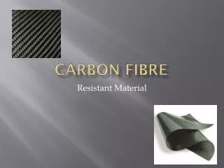
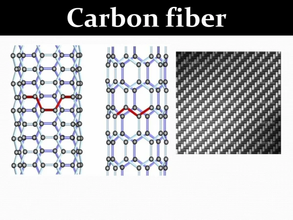
What are Carbon Fibre Composites • Multi layers of long carbon fibres which have been impregnated into a polymer matrix • In each layer the fibre direction is pointing along different orientations Illustration of few layers of CFC [1] [1] Composite material revolutionise aerospace engineering, Ingenia, 2008, http://www.ingenia.org.uk/ingenia/issues/issue36/edwards.pdf
Purpose of this Study a) • Growing interesting in using Carbon Fibre Composite (CFC) as a high tech construction material. Examples: Wind turbines & Aircraft, • This is due to CFC having: • High strength • Low weight • Problem: Unlike traditional building materials (aluminium), CFC are highly anisotropic and are poor electrical and thermal conductors • Aim: Optimise the CFC Layout to reduce the damage caused. This will be done by building a numerical model to investigate the physical processes which result from a lightning strike impacting CFC b) Images show the typical damage from a lightning strike to a) Carbon Fibre Composite [2] and b) Aluminium [3] [2]Feraboli, P. and M. Miller, Damage resistance and tolerance of carbon/epoxy composite coupons subjected to simulated lightning strike. Composites Part A: Applied Science and Manufacturing, 2009. 40 (6-7): p. 954 - 967 [3] Uhlig, F., Contribution `a l’´etude des effets directs du foudroiement sur les mat´eriaux structuraux constituant un a´eronef. 1998, Universit´e de Paris.
Main Physical Components • Initial Carbon fibre composite material CFC Cross section
Main Physical Components • Initial Carbon fibre composite material • Two inputs into the system: • Heat flux from the plasma channel • Injection of current into the material Plasma channel Injected Current
Main Physical Components • Initial Carbon fibre composite material • Two inputs into the system: • Heat flux from the plasma channel • Injection of current into the material • Temperature profile in the material due to volumetric Joule heating and the plasma heat flux Temperature profile
Main Physical Components • Initial Carbon fibre composite material • Two inputs into the system: • Heat flux from the plasma channel • Injection of current into the material • Temperature profile in the material due to volumetric Joule heating and the plasma heat flux • Thermal-chemical degradation (polymer pyrolysis or phase change) • Due to degradation need to consider the change in internal energy and change in materials Change in material
Main Physical Components • Initial Carbon fibre composite material • Two inputs into the system: • Heat flux from the plasma channel • Injection of current into the material • Temperature profile in the material due to volumetric Joule heating and the plasma heat flux • Thermal-chemical degradation (polymer pyrolysis or phase change) • Due to degradation need to consider the change in internal energy and change in materials • Gas transport inside material inc. conservation of energy and mass • As hot gas escapes from the degradation site – change in internal energy Gas transport
Numerical Model • Built a numerical model to replicate of physical process which occur in a CFC due to a lightning strike • The numerical model is based on an FEA approach • Main assumptions of our model: • Can assume CFC material to be a homogenous anisotropic material • Only considering the polymer pyrolysis degradation process (Previous work has shown this to be dominate degradation process) [4] • Once gas is produced (due to pyrolysis) it immediately escapes. Therefore we do not consider the gas transport process • All material properties are assumed constant with temperature • Material properties are taken for a typical CFC after a literature review [4] Chippendale, R. D. et. al. MODEL OF STRUCTURAL DAMAGE TO CARBON FIBRE COMPOSITES DUE TO THERMO-ELECTRIC EFFECTS OF LIGHTNING STRIKES, Proc. 30th International Conference on Lightning Protection
Numerical Model Verification – Experiment? • Experimental verification was conducted by decoupling the thermal physical process from the electrical process by using a laser with a well controlled power input • Damaged sample was then investigated using X-ray Tomography -From these scans the spatial extent of the damage can be determine • Previous simulations have shown that the majority of volumetric Joule heating occurs in top few CFC layers. Therefore the joule heating from a lightning strike can be roughly approximated to surface heating
Experimental Set-up • Experiment was set up as shown below • A 6W laser beam operating in 00 mode • Laser beam had 2mm beam diameter • Laser beam radiated the CFC for 180 s continuously • A power density of the chosen laser beam has approximately to be comparable to that of a lightning strike – however the total power input is different CFC CFC 7mm 2mm Laser beam source Laser beam Side view Top view of sample
Experimental Results • Cross section X-ray tomography image shown: black is no CFC material, grey is CFC material • Gas was visible given off during first 30 seconds and then stopped being visibly produced • Very localised damage • No damage visible on sides CFC • Most of the damage is limited to the top two layers • Carbon fibre evaporation is noticed 4.2 mm 0.5 mm
Comparison • Similar shape in damage in damage • Reasonable agreement between the spatial extent of the damage Volume fraction of polymer (φ) Numerical Model Experimental Results 8 mm 0.6 4.6 mm 7 mm 6.37 mm Top down Z X 0 mm 0.3 7.4 mm 0 mm 10 mm 4 mm 2 mm 2.25 mm 4.2 mm Cross section 0.5 mm 0.5 mm Y 0 0 mm 10 mm 0 mm X 5 mm
Conclusion • Damage predicted by numerical model agrees fairly accurately with the experimental results • Possible reasons for inaccuracies: • No exact material properties are known (thermal conductivity, pyrolysis energies) • No gas transport included • Next steps: Inclusion of gas transport
Main Physical Components Plasma surface heating around attachment area Temperature profile inside material Lightning strike current Profile Thermo-Chemical degradation (phase change & pyrolysis) Thermo-mechanical response – differential thermal expansion, delamination of CFC ply and internal cracks (not included here) Electrical conduction resulting in volumetric joule heating Gas transport in material inc. Conservation of energy and mass Variation in bulk material properties