Download
1 / 48
580 likes | 1.72k Vues
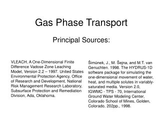
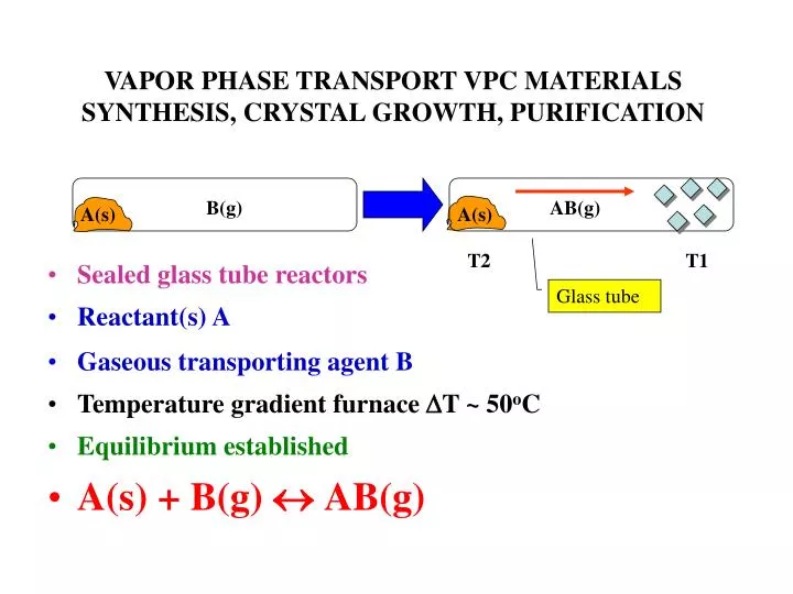
B(g). AB(g). A(s). A(s). VAPOR PHASE TRANSPORT VPC MATERIALS SYNTHESIS, CRYSTAL GROWTH, PURIFICATION. Sealed glass tube reactors Reactant(s) A Gaseous transporting agent B Temperature gradient furnace D T ~ 50 o C Equilibrium established A(s) + B(g) « AB(g). T2. T1. Glass tube.

E N D
B(g) AB(g) A(s) A(s) VAPOR PHASE TRANSPORT VPC MATERIALS SYNTHESIS, CRYSTAL GROWTH, PURIFICATION • Sealed glass tube reactors • Reactant(s) A • Gaseous transporting agent B • Temperature gradient furnace DT ~ 50oC • Equilibrium established • A(s) + B(g) « AB(g) T2 T1 Glass tube
B(g) AB(g) A(s) A(s) T2 T1 VAPOR PHASE TRANSPORT VPC MATERIALS SYNTHESIS, CRYSTAL GROWTH, PURIFICATION Glass tube • Equilibrium constant K • A + B react at T2 • Gaseous transport by AB(g) • Decomposes back to A(s) at T1 • Creates crystals of pure A
B(g) AB(g) A(s) A(s) T2 T1 VAPOR PHASE TRANSPORT VPC MATERIALS SYNTHESIS, CRYSTAL GROWTH, PURIFICATION • Temperature dependent K • Equilibrium concentration of AB(s) changes with T • Different at T2 and T1 • Concentration gradient of AB(g) provides thermodynamic driving force for gaseous diffusion from T2 to T1 Glass tube
THERMODYNAMICS OF CVT • A(s) + B(g) AB(g) • Reversible equilibrium needed: DGo = -RTlnKequ • Consider case of “exothermic” reaction with - DGo • Thus DGo = RTlnKequ • Smaller T implies larger Kequ • Forms atcoolerend - decomposes athotterend of reactor • Consider case of “endothermic” reaction with +DGo • Thus DGo = -RTlnKequ = RTln(1/Kequ) • Larger T implies larger Kequ • Forms athotterend - decomposes atcoolerend of reactor
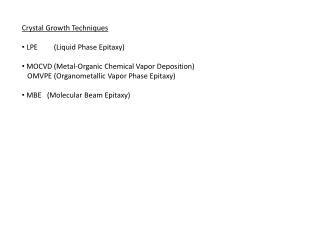
USES OF VPT • synthesis of new solid state materials • growth of single crystals • purification of solids
PtO2(g) Pt(s) VPT agent PtO2(g) Atmosphere O2(g) PLATINUM HEATER ELEMENTS IN FURNACES THEY MOVE!! Pt(s) + O2(g) « PtO2(g) • Endothermic reaction • PtO2 forms at hot end • Diffuses to cool end • Deposits well formed Pt crystals • Observed in furnaces containing Pt heating elements • CVT, T2 > T1, provides concentration gradient and free energy thermodynamic driving force for gaseous diffusion of vapor phase transport agent PtO2 T2 T1
APPLICATIONS OF CVT METHODS • Purification of Metals • Van Arkel Method • Cr(s) + I2(g) (T2) « (T1) CrI2(g) • Exothermic, CrI2(g) forms at T1, pure Cr(s) deposited at T2 • Useful for Ti, Hf, V, Nb, Cu, Ta, Fe, Th • Removes metals from carbide, nitride, boride, silicide, oxide impurities!!!
DOUBLE TRANSPORT INVOLVING OPPOSING EXOTHERMIC-ENDOTHERMIC REACTIONS • Endothermic • WO2(s) + I2(g) (T1 800oC) « (T2 1000oC) WO2I2(g) • Exothermic • W(s) + 2H2O(g) + 3I2(g) (T2 1000oC) « (T1 800oC) WO2I2 (g) + 4HI(g) • The antithetical nature of these two reactions allows W/WO2 mixtures which often form together to be separated at different ends of the gradient reactor using H2O/I2 as the VPT reagents
VAPOR PHASE TRANSPORT FOR SYNTHESIS • A(s) + B(g) (T1) «(T2) AB(g) • AB(g)+ C(s) (T2) « (T1)AC(s)+B(g) • Concept: couple VPT with subsequent chemical reaction to give overall reaction and desired product : • A(s) + C(s) + B(g) (T2) « AC(s) + B(g) (T1)
REAL EXAMPLES VPT SYNTHESIS DIRECT REACTION • SnO2(s) + 2CaO(s) ® Ca2SnO4(s) • Sluggish reaction even at high T for a useful phosphor • Greatly speeded up with CO as VPT agent • SnO2(s) + CO(g)« SnO(g) + CO2(g) • SnO(g) + CO2(g) + 2CaO(s) « Ca2SnO4(s) + CO(g)
REAL EXAMPLES VPT SYNTHESISDIRECT REACTION • Cr2O3(s) + NiO(s) ® NiCr2O4(s) • Greatly enhanced rate to magnetic Spinel with O2 VPT agent • Cr2O3(s) + 3/2O2« 2CrO3(g) • 2CrO3(g) + NiO(s) « NiCr2O4(s) + 3/2O2(g)
OVERCOMING PASSIVATION IN SOLID STATE SYNTHESIS THROUGH VPT • Al(s) + 3S(s) ® Al2S3(s) passivating skin stops reaction • In presence of cleansing VPT agent I2 skin removed to reveal fresh Al surface to react with S according to: • Endothermic: Al2S3(s) + 3I2(g) (T1 700oC) « (T2 800oC) 2AlI3(g) + 3/2S2(g) • Zn(s) + S(s) ® ZnS(s) passivation prevents reaction proceeding to completion and again I2 cleans surface of ZnS to reveal fresh Zn to react with S according to: • Endothermic: ZnS(s) + I2(g) (T1 800oC) « (T2 900oC) ZnI2(g) + 1/2S2(g)
Fe3O4(s) 1270K 1020K VPT agent FeCl2/FeCl3(g) Atmosphere HCl(g) VPT GROWTH OF FERROMAGNETIC MAGNETITE CRYSTALS FROM POWDERED MAGNETITE • Endothermic reaction forms at hotter end and crystallizes at cooler end according to the VPT reaction • Fe3O4(s) + 8HCl(g) 1020K 1FeCl2(g) + 2FeCl3(g) + 4H2O(g) 1270K • Inverted Spinel ferromagnetic Magnetite crystals grow at cooler end - B(AB)O4 - Fe(III)(Td)[Fe(III)Fe(II)(Oh)]O4
FERROMAGNETIC INVERTED SPINEL MAGNETITE B(AB)O4Fe(III)(Td)[Fe(III)Fe(II)(Oh)]O4 Field H Multidomain paramagnet above Tc Multidomain ferromagnet below Tc M Ms Mr Single domain superparamagnet Hc H Magnetization Hysteresis M vs H Diagnostic of Ferromagnetism
TiS2 Ti/S(s) 550-685oC (T2) 510-645oC (T1) VPT agent TiBr4(g) Atmosphere Br2(g) VPT SYNTHESIS AND CRYSTAL GROWTH OF TiS2 FROM POWDERED Ti/S • Endothermic reaction forms at hotter end and crystallizes at cooler end - also removes passivating TiS2 skin on Ti • (T1) TiS2(s) + 2Br2(g) (T2) TiBr4(g) + S2(g) • TiS2 plate morphology crystal grow at cooler end • Interesting for studying intercalation reactions - kinetics, mechanism, structure • Relevant to use of TiS2 as a LSSB cathode
Li insertion LITHIUM SOLID STATE BATTERY MATERIAL Li + TiS2 LixTiS2 • TiS2 structure hcp packing of S(-II) 3pp filled VB, octahedral Ti(IV) t2g 3d empty CB • Li+ intercalates between hcp S2- layers into well defined LiS4 Td crystallographic sites • Charge balancing electrons injected into t2g Ti(IV) CB • TiS2 semiconductor, LixTiS2 conductivity increases upon insertion of Li(+) and e(-) • Hopping semiconductor mixed valence description xLi(I)xTi(III)(1-x)Ti(IV)S2 • Li intercalation varies from 1 x 0, 10% lattice expansion, TiS2 LiTiS2 • Microscopic intercalation manifest macroscopically – expansion of thickness of plate crystal • Capacity ~ 250 A-h/kg, Voltage ~ 1.9 Volts - too low for SS cathode • Energy density ~ 480 W-h/kg
1060oC (T2) ZnWO4(s) 980oC (T1) WO3/ZnO(s) VPT SYNTHESIS OF ZnWO4A REAL PHOSPHOR HOST CRYSTAL FOR LUMINESCENT Ag(I), Cu(I), Mn(II)Isomorphous Replacement of Non-Luminescent Zn(II) Cations by Luminescent Ones • WO3(s) + 2Cl2(g) (T2 1060oC) « (T2 1060oC) WO2Cl2(g) + Cl2O(g) • WO2Cl2(g) + Cl2O(g) + ZnO(s) (T2 1060oC) « ZnWO4(s) + Cl2(g) (T1 980oC) Endothermic reaction VPT agent WO2Cl2(g) + Cl2O(g) formed at hot end in an atmosphere Cl2(g)
(T1) GaAs(s) GaAs(s) (T2) VPT GROWTH OF EPITAXIAL GaAs FILMS ON LATTICE MATCHING SUBSTRATE OR GROWTH OF SINGLE CRYSTALS USING CONVENIENT STARTING MATERIALS GaAs(s) + HCl(g)« GaCl(g) + 1/2H2(g) + 1/4As4(g) Endothermic VPT agent GaCl/As4/H2(g) formed at hot end in an atmosphere of HCl(g)
MgB2 SAT ON THE SHELF DOING NOTHING FOR HALF A CENTURY AND THEN THE BIGGEST SURPRISE SINCE HIGH Tc CERAMIC SUPERCONDUCTORS
SUPERCONDUCTIVITY IN MgB2 AT 39KA SENSATIONAL AND CURIOUS DISCOVERY Mg B Mg Note basic repeat unit is 1Mg + 6/3B = MgB2
E p* 3p-p* 3p 3s-* p 3s 3p-p 3s- N(E) BONDING AND ELECTRONIC STRUCTURE IN MAGNESIUM DIBORIDE - DOS - THINKING ABOUT ORIGIN OF SUPERCONDUCTIVITY IN MgB2 Graphite like B22- MgB2 Mg2+
BCS THEORY OF SUPERCONDUCTIVITYTc =1.13hwD/2pkB{exp[-1/N(EF)V]} DOS of electrons at Fermi level - larger N(EF) - larger Tc Matrix element characteristic of e-ph-e coupling of Cooper pairs - larger V - larger Tc - requires high frequency phonon modes Debye cut off frequency - highest phonon mode - temperature dependent, wD m-1/2 - expected isotope effect on (Tc(m1)/Tc(m2) = (m2/m1)1/2
SUPERCONDUCTIVITY IN MgB2 AT 39K A SENSATIONAL AND CURIOUS DISCOVERY • Metallic MgB2 known since 1953 • Direct synthesis from reacting Mg/B solids • Akimitsu Nature 2001, 410, 63 • Tc of 39K, surprising • Tc Nb3Ge 23K, LaxSr1-xCuO4 40K, YBa2Cu3O7 90K • Graphitic B22- sheets sandwiching hcc Mg2+ layers • Isoelectronic graphite NOT a superconductor – but when doped C8K Tc = 0.15K
SUPERCONDUCTIVITY IN MgB2 AT 39K A SENSATIONAL AND CURIOUS DISCOVERY • Strong 3p-p bonding interactions between B6 rings and Mg • Band diagram 3p-p stabilized wrt 3s-* of graphitic-like B22- sheets • BCS Isotope effect of 1K on Tc for Mg10B2 higher than Mg11B2 implicates phonons • Cooper pairs (e-p-e coupling) generated by excitation of 3p-p electrons into 3s-* • MgxAl1-xB2stronger Al3+ 3p-p, larger 3p-p/3p-p* gap • Fewer Cooper pairs, lower Tc
SURPRISE-SURPRISE NATURE PHYSICS 2005, 1, 39HIGH TC INTERCALATED SUPERCONDUCTING C6Y AND C6Ca GRAPHITES - VPT OF Yb AND Ca INTO GRAPHITE XRD shows every layer filled with Yb, stage 1, interlayer spacing 4.57 Å, AA registered graphite layers and a-b offset triangular array Yb layers, superconductivity mechanism under investigation
Sealed quartz tube B/I2/Si/1100°C BI3/SiI4 VPT Tantalum tube MgO/5nm Au/B NWs/VLS 1000°C MgB2 NWs B NWs-MgO/Mg/800-900°C VPT AND VAPOR-LIQUID-SOLID (VLS) SYNTHESIS OF BORON NANOWIRES AND THEIR CONVERSION TO SUPERCONDUCTING MgB2 NANOWIRES
VPT AND VAPOR-LIQUID-SOLID (VLS) SYNTHESIS OF BORON NANOWIRES AND THEIR CONVERSION TO SUPERCONDUCTING MgB2 NANOWIRES AuSi dewetting on MgO on heating and nano cluster formation on MgO VLS growth of B NWs on AuSi clusters Au film on MgO
CONVERSION OF B NANOWIRES TO SUPERCONDUCTING MgB2 NANOWIRES B NWs on AuSi clusters MgB2 NWs on AuSi clusters Mg 800-900°
SYNTHESIS OF SUPERCONDUCTING MAGNESIUM BORIDE NANOWIRES • Planar hexagonal net of stacked B2- anionic layers with hexagonally ordered Mg2+ cations between the layers • VPT agent BI3/SiI4 • VLS growth of B NWs, diameter 50-400 nm, on controlled size AuSi nanoclusters supported on MgO substrate • Vapor phase transformation of amorphous boron nanowires tocrystalline magnesium boride nanowires B MgB2
SUPERCONDUCTIVITY OF MAGNESIUM BORIDE NANOWIRES • Magnetization of MgB2 nanowires as a function of temperature under conditions of zero field cooling and field cooling at 100G –latter uncouples Cooper pairs former maintains them • The existence of superconductivity within the sample is demonstrated by these measurements of perfect diamagnetism and the Meissner effect at ~ 33K of total exclusion of an external magnetic field (diamagnetic supercurrent and Lenz’s law) • Potentially useful as building blocks in superconducting nanodevices and as low power dissipation interconnects in nanoscale electronics • Recently epitaxial thin films made for superconducting electronics and nanohelices! ZFC Tc
Meissner Effect • The Meissner effect is the total exclusion of any magnetic flux from the interior of a superconductor • It is often referred to as perfect diamagnetism • In the effect, there is an exclusion of magnetic flux brought about by “electrical screening currents" that flow at the surface of the superconductor and which generate a magnetic field that exactly cancels (repels) the externally applied field inside the superconductor (Lenz’s law). • The Meissner effect is one of the defining features of superconductivity, and its discovery served to establish that the onset of superconductivity is a phase transition between uncoupled and phonon coupled electrons • Superconducting magnetic levitation is due to the Meissner effect which repels a permanent magnet Mag Lev high speed train
SUPERCONDUCTING MAGNESIUM DIBORIDE HELICESSuperconducting nanocoils and solenoids (with iron nanorod cores) may have practical applicationsas nanoactuators or in flexible superconducting cable. Mg(s) + B2H6 (770-800 °C VPT flow of N2 and H2) MgB2
RT ULTRAVIOLET ZnO NANOWIRE NANOLASERSVPT SYNTHESIS AND GROWTH
RT ULTRAVIOLET NANOWIRE NANOLASERSVPT SYNTHESIS AND GROWTHVPT carbo-thermal reductionZnO/C 905°C ===> ZnCO VPT ===> ZnO VLS NW880°C
ZnO/C/905°C ZnCOVPT VPT AND VLS SYNTHESIS AND GROWTH OF ORIENTED ZnO NANOWIRES Sealed quartz tube reactor - fate of carbon deposited on glass VLS growth ZnO wires on 1-3.5 nm Aun nanoclusters on sapphire 880°C Alumina boat
VPT-VLS SYNTHESIS AND GROWTH OF ORIENTED ZnO NANOWIRES ZnO <0001> growth ZnCO C Aun sapphire
ZnO NW LASER 266 nm excitation 385 nm laser emission
RT ULTRAVIOLET NANOWIRE NANOLASERS • RT UV e-h excitonic lasing action in ZnO nanowire arrays demonstrated • Self-organized <0001>oriented ZnO nanowires grown (epitaxially) on 1-3.5 nm thick Au coated sapphire substrate, dewetting makes Au nanoclusters – thickness of Au film controls diameter of Au nanocluster – ZnO nanowires grow from Au nanoclustrs - nanowiremorphology related to fastest rate of growth of <0001> face • VPT carbothermal reduction ZnO/C 905°C ZnCO ZnO VLS NW growth at 880°C alumina boat, Ar flow, condensation process • Wide band-gap ZnO SC nanowires, faceted end and epitaxial sapphire end reflectors, high RI ZnO that is cladded by lower RI air and sapphire form natural TIR laser cavities, nanowire diameters 20-150 nm with lengths up to 10 mm
RT ULTRAVIOLET NANOWIRE NANOLASERS • PXRD pattern of ZnO nanowires on a sapphire substrate • Only (000l) peaks observed owing to well-oriented <0001> growth • (A) PL emission spectra from nanowire arrays below (line a) and lasing emission above (line b and inset) the threshold, pump power for these spectra are 20, 100, and 150 kW/cm2 , respectively. • (B) Integrated emission intensity from nanowires as a function of optical pumping energy intensity
RT ULTRAVIOLET NANOWIRE NANOLASERS • (C) Schematic of a nanowire as a resonance cavity with two naturally faceted hexagonal end faces acting as reflecting mirrors • Stimulated emission from the nanowires collected in the direction along the nanowire’s end-plane normal (the symmetric axis) • The 266-nm pump beam focused on nanowire array at angle 10° to the end-plane normal, all experiments were carried out at RT
RT ULTRAVIOLET NANOWIRE NANOLASERS • QSEs yield substantial DOS at band edges and enhances e-h radiative recombination due to carrier confinement • Under 266 nm optical excitation, surface-emitting lasing action observed at 385 nm with emission line width < 0.3 nm • The chemical flexibility and the one-dimensionality of these quantum confined nanowires make them ideal miniaturized laser light sources • UV nanolasers and patterned arrays could have myriad applications, including optical computing, information storage and on chip microanalysis
GaN NW LASER - TOPOGRAPHIC AND OPTICAL IMAGE OF UV LASING ACTION – NW END EMISSION SEEN
VLS SYNTHESIS AND GROWTH OF ORIENTED GaN NANOWIRES Wurtzite type GaN <0001> growth Ga or Me3Ga/NH3/900°C sapphire Nin
individual GaN NW UV lasing action Lasing from ends lasing photoluminescence
COMBINATORIAL Ga1-xInxN NANOWIRE SYNTHESIS FULL COLOR TUNING OF PHOTOLUMINESCENCE The reactor consists of three inner quartz tubes, which supply the reactive gases, InCl3, GaCl3 (N2 carrier) and NH3, and an outer quartz tube, which supplies inert gas (N2) and houses the reaction in a horizontal tube furnace. Two independently controlled heating tapes were used to tune the vapour pressure of the InCl3 and GaCl3 precursors. The positioning of the reactive gas outlets results in the observed InGaN compositional gradient. Shown below the furnace is the temperature profile, indicating that the centre of the furnace is maintained at 700 C, whereas the substrates are at 550 C. Inset: Photograph of an as-made sample on quartz (left) and a colour image from PL of a section of substrate (right).
COMBINATORIAL Ga1-xInxN NANOWIRE SYNTHESISVegard’s Law on Unit Cell Dimensions and Electronic Bandgap Wire morphology and XRD at varying InGaN composition. a, SEM images of the nanowire morphology, with increasing In concentration from images 1 to 13. The wire morphology changes most noticeably in 10–11 from the smaller to larger wires at around 75–90% In. b, 100, 002 and 101 XRD peaks from left to right of the nanowires, with increasing In concentration from images 1 to 13. c, Lattice constants a and c derived from the 100 and 002 diffraction peaks respectively, plotted as a function of In concentration determined by EDS, and Vegard-law values for the respective a and c lattice constants as a function of indium concentration (red and blue lines).
COMBINATORIAL Ga1-xInxN NANOWIRE SYNTHESISVegard’s Law on Unit Cell Dimensions and Electronic Bandgap The data were fitted by the following standard bowing equation: F(x)=P1(1−x)+P2x−Bx(1−x),where F(x) is the energy gap as a function of composition x. P1 and P2 represent the bandgaps at x =0 and x =1 respectively, and B is the bowing parameter. The following values were obtained: GaN, P1 = 3.43 eV; InN, P2 = 1.12 eV;B = 1.01 eV. Optical characterization of the InGaN nanowires. a, Colour CCD images, b, visible PL emission (x =0–0.6), c, corrected peak intensities and d, optical absorption spectra (x =0–1.0) of the InxGa1−xN nanowire arrays taken at intervals across the substrates with varying concentration x. e, Energy plotted as a function of In concentration x determined by EDS for PL, absorption and EELS and bowing equation fit to absorption spectra.