Electric headlight starter (ignition device)
100 likes | 261 Vues
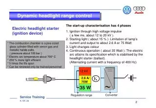
Dynamic headlight range control. The start-up characterisation has 4 phases 1. Ignition through high voltage impulse ( a few ms, about 12 to 20 kV ). 2. Starting light ( about 15 % ): Limitation of lamp's current and output to about 2.6 A or 75 Watt 3. Light changes colour

Electric headlight starter (ignition device)
E N D
Presentation Transcript
Dynamic headlight range control The start-up characterisation has 4 phases 1. Ignition through high voltage impulse ( a few ms, about 12 to 20 kV ). 2. Starting light ( about 15 % ): Limitation of lamp's current and output to about 2.6 A or 75 Watt 3. Light changes colour 4. Continuous operation ( about 35 Watt ): The electric arc attains its specification which is stabilised by the headlight starter (ballast). (Alternating current with a frequency of 400 Hz) Electric headlight starter (ignition device) * The combustion chamber is a pea-sized glass cylinder filled with xenon gas and metallic halide salts. ( pressure about 100 bar ) * Electric arc temperature about 700° C * 250 % more light efficient * 5 times the life span * Can be renewed only by trained personnel 12 kV 2.6 A/ 75W 35 W Converter Regulation range
M Dynamic headlight range control Functional diagram Headlight range control Terminal 15 Terminal 31 Terminal 65b V 48 left G 78 6 2 17 10 9 3 5 2 4 19 15 3 4 20 J 431 1 7 8 6 6 M Headlight range control CU on left inluggage compartment 16 2 3 13 14 11 12 4 G 76 V 49 right V signal K wire Failure warning light in estate ( Audi only ) CAN ( to be used later )
Angle of rotation 70° Dynamic headlight range control Contactless attitude sender operating on Hall principle The senders are identical to those of the static headlight range control ( see also Trainer Information Audi A6 ) Vehicle attitude sender G 76 / G 78 Design N Ring magnet N Stator S Hall sender S High magnetic field density Low magnetic field density 4.5 2.5 0.5 0 V
Dynamic headlight range control Address word 55 Coding 00007 for front wheel drive 00008 for four-wheel drive Final control diagnosis Lower/raise headlights Measured value blockChannel 001 1 = Voltage supply terminal 15 ( in Volt ) 2 = Light switch terminal 56b (light on/off ) 3 = Speed in km per hour 4 = Vehicle acceleration in m/s² Channel 002 1 = Front attitude sender in Volt ( 1.57 to 3.45 Volt ) 2 = Rear attitude sender in Volt ( 1.57 to 4.5 Volt ) 3 = Step motor actuation in % ( indicates what percent of the spindle is advanced from the zero position ) 4 = Time constant in seconds ( time required for 63 % of the adjustment to occur ) Basic setting Channel 01 Regulating mode is switched off Channel 02 Control unit learns the adjusted position as regulation position Headlight range control self-diagnosis
Vehicle self-diagnosis 08 - Read measured value block Read measured value block Display group Basic setting 55 Headlight range control 4B0 907 357C Dynamic HRC D03 7 Coding 7 Dealership number 1317 Voltage supply terminal 15 12.1 V Light switch off/on 0 / 1 Vehicle speed 0 km/h Vehicle acceleration in m/s2 0.00- 7.00 m/s2 1 Coding = 7 Front wheel drive 8 Four-wheel drive
Vehicle self-diagnosis 08 - Read measured value block Read measured value block Display group Basic setting 55 Headlight range control 4B0 907 357C Dynamic HRC D03 7 Coding 7 Dealership number 1317 Front vehicle attitude sender (1.57 to 3.45 V ) 3.1 V 2.3 V Rear vehicle attitude sender (1.57 to 4.50 V ) Step motor actuation in % ( 0 to 100% ) * 74 % Time constant in seconds ( 0 to 2 seconds ) ** 0.03 s 2 * indicates what percent of the spindle is advanced from zero postion of step motor ** indicates time required for headlights to attain 63% of their adjustment
Vehicle self-diagnosis 03 - Final control diagnosis Read measured value block Display group Basic setting 55 Headlight range control 4B0 907 357C Dynamic HRC D03 7 Coding 7 Dealership number 1317 12.1 V For basic setting, leave lights on and engine running 0 / 1 0 km/h 0.00- 7.00 m/s2 1 Adjusting headlights
Vehicle self-diagnosis 03 - Final control diagnosis Read measured value block Display group Basic setting 55 Headlight range control 4B0 907 357C Dynamic HRC D03 7 Coding 7 Dealership number 1317 3.1 V For basic setting, leave lights on and engine running 2.3 V 74 % 0.03 s 2 Regulation position being learnt
Vehicle self-diagnosis 03 - Final control diagnosis Read measured value block Display group Basic setting 55 Headlight range control 4B0 907 357C Dynamic HRC D03 7 Coding 7 Dealership number 1317 Headlights will be lowered Headlights will be raised Signal wire to combi-instrument 3