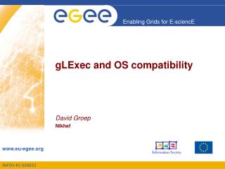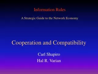
Compatibility and Interoperability
This meeting discusses the compatibility and interoperability of GNSS systems, focusing on RF interference, signal separation, and system-to-system interactions to ensure optimal performance. Key factors and calculations are explored in detail.

Compatibility and Interoperability
E N D
Presentation Transcript
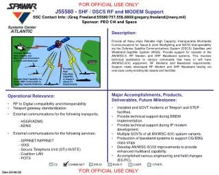
Compatibility and Interoperability Meeting of GNSS Experts 5 September 2007 Tom StansellAerospace Corporation Consultant to GPS Wing
Definition of Compatibility • “Compatible” refers to the ability of U.S. and foreign space-based positioning, navigation, and timing services to be used separately or together without interfering with each individual service or signal
Radio Frequency Compatibility • Ensures that signals do not unacceptably interfere with use of other signals • Requires thorough consideration of detailed technical factors, including • Effects on receiver noise floor • Crosscorrelation between interfering and desired signals • International Telecommunication Union (ITU) provides framework • Details are best worked bilaterally between providers
U.S. Objectives in Working with Other GNSS Service Providers • Ensure compatibility • Radio frequency compatibility • Spectral separation between M code and other signals • See following example • Achieve interoperability between GPS civil signals and other system’s civil signals • Primary focus on the common L1C and L5 signals
M Code signal is spectrally separated from civil signals Civil Signals M Spectral Separation of GPS Civil and M-code Signals in L1
Interference and Compatibility • GNSS has many sources of RF interference • Radio sources other than RNSS* – “Other” • Often characterized by significant near-far power variations • Intra-System interference (system self interference) • Inter-System interference (one system to another) • Unlike the essentially uncontrolled near-far problem of terrestrial interference sources, satellite systems are in a known orbital configuration • Compatibility refers to Inter-System interference • All sources of interference are important to determining inter-system compatibility *RNSS = RadioNavigation Satellite Service
Determining RF Compatibility (1 of 2) • RF compatibility (RFC) is determined by the extent that one RNSS interferes with reception of another RNSS’s signals • RFC must account for two phenomena: • Interfering signals contribute to the additive random background in which the receiver processes the desired signal • Interfering signals may be correlated with the desired signal, inducing a receiver to falsely detect or track an interfering signal
Determining RF Compatibility (2 of 2) • One way of determining interference effects on additive random background is based on: • Nominal receiver with specified noise figure and receive antenna • Received desired signal at its minimum specified received power, including polarization mismatch • Using the smallest receive antenna gain over elevation angles the system is specified to support • Nominal worst-case external interference • Nominal worst-case intra-system interference • Nominal worst-case interference from other systems • Then evaluating whether the received signal, noise, and interference enable adequate receiver performance
Typical Antenna Patterns Typical satellite antenna patterns (left) and receiver antenna patterns (right) are used to determine largest aggregate intrasystem and intersystem interference power over time and locations on earth
Example of Maximum Aggregate Interference Power Distribution
Gagg Analysis • Aggregate interference gain (Gagg) is defined as the ratio between the maximum (over time and location on earth) received interference power and the maximum received power from a single satellite • Typical Gagg values range from 7 dB for a regional RNSS to greater than 12 dB for a large GNSS constellation
× integrate and dump r(t) desired signal, c(t) Spectral Separation Coefficient • An important compatibility factor is the extent to which undesired signals contribute interference • How much additional interference is caused by undesired received signals r(t) when they are correlated with a desired spreading code? • The “undesired” signals may be from the same RNSS or another RNSS • Intrasystem and intersystem interference respectively • This is determined by the Spectral Separation Coefficient (SSC) between signals RFC assessment based in part on interference after correlating with desired signal Only one of many received signals is “desired”
The SSC Calculation (1 of 2) Provided by Dr. Chris Hegarty • With long spreading codes and many visible satellites, can treat intersystem and intrasystem interference as stochastic and Gaussian • With normalized power spectral density (psd) = Gk(f) • Desired signal also treated as stochastic with psd = Gs(f) • Multiplier output psd is convolution of input psd’s for interference that is “independent” of desired spreading code • DC value is inner product of input psd’s • Equation on next page presumes DC value represents average density across integrate and dump filter bandwidth
The SSC Calculation (2 of 2) Provided by Dr. Chris Hegarty • SSC computation for GNSS signals with very long spreading codes is straightforward: • Specific conventions must be established for details of the SSC calculation • Interference analysis based upon this SSC formula does not necessarily hold for signals with short spreading codes • This SSC describes how interference affects acquisition, carrier tracking, and data demodulation, but not code tracking
Example L1 SSC Relationships Power Spectral Density (PSD) of L1 Signals *Typical Spectral Separation Coefficients (SSC) (dB/Hz) of L1 Signals *Specific values depend upon conventions used in calculations
Example Calculation • Compute the intrasystem effective noise power spectral density (psd) contributed by other GPS MBOC signals to reception of a GPS MBOC signal • Assume max MBOC received power of -154 dBW and a Gagg of 12 dB • If MBOC on MBOC SSC is -65 dB/Hz, then effective noise psd for MBOC on MBOC interference is –207 dBW/Hz • Assume receiver noise floor of -201.5 dBW/Hz • Then GPS MBOC on GPS MBOC interference is about 5.5 dB lower than the receiver noise floor
Definition of Interoperability “Interoperable” refers to the ability of civil U.S. and foreign space-based positioning, navigation, and timing services to be used together to provide better capabilities at the user level than would be achieved by relying solely on one service or signal Interoperable = Better Together than Separate
GALILEO QZS GLONASS GPS The Goal of RNSS Civil Interoperability • Ideal interoperability allows navigation with one signal each from four different systems with no additional receiver cost or complexity
Main Benefit of Interoperability Geometry • More Satellites Better Geometry Improves: • Satellite coveragenavigate where could not before • Dilution of Precision accuracy is better everywhere • Eliminates DOP holes (with open sky) • RAIM* integrity checked everywhere, all the time • Eliminates RAIM holes (with open sky) • Phase ambiguity resolution for survey and machine control applications * Receiver Autonomous Integrity Monitoring
Important for Interoperability Essential (cost driver) • Common Center Frequency • Like L5 & E5a • Same Antenna Polarization • Common Signal Spectrum • Identical receiver time delay with common spectrum • Same coherent integration period for acquisition • Usually related to symbol rate • Different symbol rates may require separate search correlators for acquiring signals Important (no time bias or filter issues) Desirable (ASIC gate count)
Other Interoperability Factors (1 of 3) • Some signal characteristics have very little impact on interoperability • This is because of the continuing evolution in digital electronic capabilities and costs (Moore’s Law) • If signal differences can be accommodated digitally, the impact on cost, size, weight, and power is minimal and will continue to decline • Examples are message structure and content, forward error correction (FEC) technique, and method of multiplexing signal components (e.g., data and pilot carrier) by time division (as in L2C) or I and Q phase components (as in L5)
Other Interoperability Factors (2 of 3) • System time offset may affect interoperability, depending on the circumstance • This is why system time offset parameters will be part of future GPS, Galileo, and QZSS messages • Permits use of only one or two extra satellites • Conversely, GPS and GLONASS receivers function well without a time offset message • Receivers compute and remember time offset, to high precision, if 2+3 or more satellites are in view • Time offset is a slowly changing solution variable • No impact with common differential corrections • From the same reference station or network
Other Interoperability Factors (3 of 3) • Geodesy differences may affect interoperability, depending on the extent of the differences • Much progress in eliminating geodesy offsets • Continuing work is underway • Current GNSS geodesy models are so nearly equivalent that most users are not affected • Coordinate system differences are known and can be applied in the receiver software • Also, no impact with common differential corrections
Summary • GNSS compatibility is vital • GNSS interoperability benefits civil users • Bilateral GNSS working groups have been very effective • Both parties benefit from cooperation • Assuring compatibility between systems • Promoting interoperability of civil signals
Determine Compatibility Assumptions System characteristics Methodology Calculation method Criteria Tolerance Key Parameters(Backup Slide) Aggregate Gain = Gagg