Signaling System 7
Signaling System 7. In the Old Days. PST – Per trunk Signaling This method was used to set up calls between telephone company exchanges. Still used in some parts of the world but use is declining, according to the text – pg 88, PBX’s use this to communicate with the CO

Signaling System 7
E N D
Presentation Transcript
In the Old Days.... • PST – Per trunk Signaling • This method was used to set up calls between telephone company exchanges. • Still used in some parts of the world but use is declining, according to the text – pg 88, PBX’s use this to communicate with the CO • This methods employs tones or multiple frequencies sent down the same line that is used for your voice conversations. • The tones are used to identify and monitor details of the call – request to make a call, connected call, hang-up, ring back, length of call.....
PTS continued • The information needs to be conveyed to each central office along the path of the call. • For long distance calls this can mean many offices along the way that the information must be forwarded too. • Essentially the call is being set up at each office along the way chewing up transmission time. • Calls can take up 6-12 seconds to set up, customer has to wait but, also what about the carrier? • 6 seconds times thousands of calls now mean real time lost on the system for providing billable service • 2000 calls X 6 seconds / 60 seconds / 60 minutes = 3.33 hours lost for just call setup and when the call is unanswered or busy, no income is brought in. = Problem
Inefficiency • Pg 89 of the text mentions that setup time for a single call could take as long as 24 seconds. • Calls can then time out and not be completed. • How many customers would wait that long with no indication that the call is going through? • What if a network was connecting hundreds of millions of calls per day – think of the lost bandwidth as well as the revenue. • Bandwidth needs equates to trunking capacity, if bandwidth needs go up additional trunking must be employed to match capacity needs. = $$$$
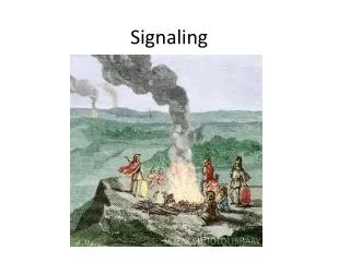
Evolution to a better system is needed • In the beginning, operators had to be told where the call was going and who it was going too. • An undertaker comes into play • A system is implemented to have calls automatically routed to a local end point. • Calls needed to go out of the coverage area – long distance. • Standards needed to be set to establish how to convey the information from one office to another • Call setup, duration, location..., information had to be conveyed along the path. • In band signaling was developed to alert the exchanges along the way. • Time on the trunks and customers having to wait pushed the need for a better system.
Problems with in-band signals • call setup time chewed into the Bandwidth • Customers had to wait while the call was being setup • Theft • An early phreaking tool, the blue box is an electronic device that simulates a telephone operator’s dialing console. It functions by replicating the tones used to switch long-distance calls and using them to route the user's own call, bypassing the normal switching mechanism. The most typical use of a blue box was to place free telephone calls - inversely, the black box enabled one to receive calls which were free to the caller.
Time to change • SS6, Signaling System 6 was the first out of band system developed • Used a separate channel to route call setup and logistical information, essentially creating an entire network that was proprietary and isolated from the public • Clears the voice trunk from other signals • Low speed links were created ~ 2400 bps, using packets of data to convey call setup and logistical information • Eliminated theft • Provided standards for exchanges and long distance carriers to send and receive information between each other • Greatly reduced call setup time • Standards were adopted by the ITU
ITU - International Telecommunication Union • ITU is the leading United Nations agency for information and communication technologies. As the global focal point for governments and the private sector, ITU's role in helping the world communicate spans 3 core sectors: radio communications, Standardization and development. • ITU is based in Geneva, Switzerland, and its membership includes 191 Member States (countries) and more than 700 Sector Members (Telecom companies) and Associates (trainers, equip. MFGs and other types of associations and related companies).
Signaling System 7 • SS7 brought improvements to the system • faster links or data channels. Both 56Kbs and 64Kbs are used. the 64Kbs is used world wide and eventually the 56Kbs circuits in the US will be upgraded t0 64Kbs. • Call setup times drop to under 1 second • Call information is exchanged including, caller ID, duration, location, end party status (busy, off hook, available, preferred long distance carrier for routing calls...) • Again, international standards allow calls to be placed seamlessly throughout the world
SS7 continued • Data packets can now vary in length, this helps increase speed and efficiency. • Allowed for remote data bases to be used by CO’s thus eliminating the need to keep the data bases current in their systems. 800 and 900 number information is kept in the remote data bases. Billing information can be kept on remote access data bases thus allowing fast access to this information. • In 2000 gateways were setup with the internet allowing for calls to go over the internet and the information to flow from SS7 to internet based services.
What would it be like if we didn’t have SS7 • Exchanges would have needed to form alliances with long distance carrier • Protocols for exchanging information would have been worked out leaving proprietary systems in place. • Choices for long distance would likely be greatly reduced • International calling would be a mess – establishing standards internationally would be next to impossible • Costs would be much higher and little to no options for alternative providers
SSP – Signal Switching Point • Switches in the central offices that connect, terminate or switch the calls. • The switches receive the information from the caller’s CPE (customer premise equipment) or phone. • If a 1-800 number is dialed the SSP knows to look up the data base on 800 numbers and finds out where the call needs to be routed. • SSPs are at the local exchanges and serves and the source and destination points along the network for SS7 information.
SCP Service Control Points • This is where the data bases reside and are accessed by the SSP’s – Signal Switching Points and the STP’s (will be covered next) • Data bases • 800 numbers • 900 numbers • Credit card verification • Call routing • Billing information • The SS7 network configuration
STP Signal Transfer Point • These are the switches that route the data packets around the network • They route the information to where it is needed, i.e. from one central office to the next, from the CO to a ILEC (Independent Local Exchange Carrier – the competition), to a switch used to connect a cellular provider, to a long distance provider... • not the actual voice information but, the data that details the needs of a specific call • Remember the voice information is setup using different links. • Note: redundant links are setup between STP’s to reroute information if a problem occurs.
SS7 Architecture The network behind the scenes
SS7 Interconnection • Pg 94 • “The actual linkage allows the local exchange offices to send the necessary information tout of the band across the signaling links. SS7 therefore uses messages in the form of packets to signal across the network the STPs. This allows the full use of the talk path for information exchange, and the messaging paths for information al dialogue between the switching systems and the transfer points. • the links are used to pass control and billing inf0ormation, network management information, and other control functions as necessary without interfering with the conversational path.”
SS7 Applications • 800/900 services • Enhancement is n800 services within call centers • 911 enhancements • Calling card toll fraud prevention • Credit card approval and authentication • Software/virtual defined private networks • Call tracing • call blocking • Caller Id
SS7 Applications continued • Local number portability • Seamless roaming in cellular networks • VoIP • Call setup in 1 second or less
Signaling System 7 • Key components • Set of standards the world can work within established under the United Nations ITU • Private Network that provides security, redundancy, common data base access, and the infrastructure to communicate the details needed for making a call locally, nationally, and internationally. • Will enable growth of new features, adjusts to market demands, packets can vary depending on the needed information • All of it works separately from the voice connection so speed, quality, redundancy, and routing can be handled without the customer being adversely affected.
Effects on signal by changing the quality of the cable – from lab • what effects did you see? • Reference – the signal straight out of the signal generator • Effects of CAT 6 • Effects of CAT 5 • What happened to the signal output of the cables when the frequency was increased.