Voltage Divider Analysis and FET Current Control in Physics Laboratory
60 likes | 182 Vues
In this module, you'll complete a pretest review and finalize your preliminary analysis of a voltage divider as part of the VI application. You will also wire up a FET current control device, specifically the IRF511 power MOSFET transistor, to measure voltage and current. Document your findings with precise data on resistance versus current for a bulb, while considering the need for delay in measurements. Utilize VI libraries for efficient data handling and report your results, including an overview of your implementation and key conclusions.

Voltage Divider Analysis and FET Current Control in Physics Laboratory
E N D
Presentation Transcript
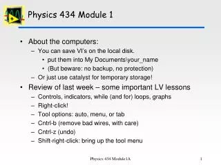
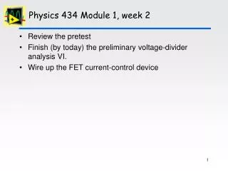
Physics 434 Module 1, week 2 • Review the pretest • Finish (by today) the preliminary voltage-divider analysis VI. • Wire up the FET current-control device
The FET: why do we need it? The IRF511 power MOSFET Transistor. Set the voltage here… And measure the voltage and current here
Requirements for your VI • Data: • current and voltage vs. applied voltage. (Nearly identical to the plot you made for the simple divider) • A hint: do not assume the “22” resistor really is! • Analysis: • Resistance vs. current for the bulb • Comments: • Beware that you will need to introduce a delay from changing the current to measuring the resulting voltage and current. Think about how to decide how much you need • The current setting of the DC voltage VI is for -10 to +10 volts: you get more accuracy if you reduce it to the range that you really need. (If you do so, this should be mentionied in your documentation
Use vi libraries (llb files) • Get from tools | VI library manager • Use New to make a new llb file • Advantages • Behaves like a folder (in Windows at least): drag/dropdouble-click to open … • SubVI’s are automatically found • Can (should) use to submitmultiple VI’s to E-submit
Turning in your VI(s) • Edit | Make current values default – needed to record your results • File | VI properties | Documentation: write a little report, containing your name(s), purpose of the VI, implementation features, conclusions.