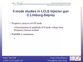
Injector Physics C.Limborg-Deprey
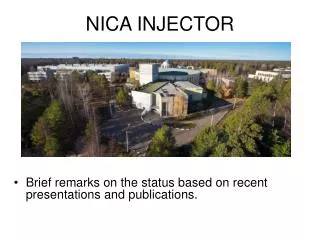
Injector Physics C.Limborg-Deprey. GTL final design Wakefield budget Final Modifications Commissioning Readiness Schedule Feedback systems An example of tuning procedure Steering in L0a. Injector. Gun installation Nov. 2006 Gun Region July 2006

Injector Physics C.Limborg-Deprey
E N D
Presentation Transcript
Injector PhysicsC.Limborg-Deprey • GTL final design • Wakefield budget • Final Modifications • Commissioning Readiness • Schedule • Feedback systems • An example of tuning procedure • Steering in L0a
Injector • Gun installation Nov. 2006 • Gun Region July 2006 • Accel Region June 2006 • Heater Region June 2006 • Wall Region October 2005 • Waveguide October 2005 • Injection Region Aug-Nov 2006 • Spect Region Aug-Nov 2006 • Injector Commissioning Start December 2006
GTL Design • Normal incidence • Mirror size (14mm x 10 mm) • No second Valve in GTL • All wakefield computed (see next slides) • Diagnostics units finalized • accommodate 20 mm screens • wakefield mitigation • Gun Solenoid moved as close as possible to cathode • Bucking Coil added (PRD written) • cancels the 55 Gauss Bz field on cathode • Compatibility with gun bake + cathode removal
GTL Design • Pending issues • <1.05 permeability of VV01 • Impact on Bsolenoid falling edge to be measured • Choice of material for injector mirror • Optical path for CRG1 light • Finalization of GTL BPMs to meet 20 m resolution • Alignment laser specifications • Final GTL design review next week Courtesy J.Langton
Wakefield Budget • projected <1.2 mm-mrad • with no error simulations show 1.0 mm-mrad • Stability of electro- magnetic components to meet less than 10% increase • <10 % increased from total wakefield effects over the whole beamline • GTL area is critical region Injection mirror with 1mm beam offset
Wakefield from Injection Mirror MAFIA Simulations, Courtesy Cho-KuenNg L (2) (3) (1) d
Wakefield Mitigation in GTL • Pumping slots • 0.24 V/pC/m per unit • 3 units at 0.6 m • 3 units at 1.2 m • Negligible emittance growth • Combined Diagnostics chambers • Wakefield Mitigated • ~small gaps Pumping slot Courtesy J.Langton Courtesy Cho-Kuen Ng
Wakefield Mitigation in GTL Bellows • Bellows • Sleeve on each 7 • Small step transition instead of 25V/pC/m Sleeve • Spectrometer bend chamber • Wakefield mitigation movable plug • Eliminates any wakefield • Small gap Straight beam • Gaps • 1mm gap ~ 3V/pC/m Beam to Spectrometer Plug out Courtesy J.Langton
Wakefield in Radiation Stopper • Radiation Stopper not an issue • LCLS-TN-05-15 "Wakefield Calculations for Radiation Stopper 1 (RST1)“ • Wrms < 0.077V/pC on axis • / < 0.1% • due to small =1.5 m MAFIA computations Courtesy Cho-Kuen Ng
Final changes in Accelerator Region Courtesy P.Stephens
Beamline Modifications • L0a moved downstream by 8 cm • Ok with emittance compensation • Solenoid 2 reduced to 20 cm effective length magnet (Req. sent out) • higher Bfield for same focal length • higher Bfield is not an issue • Suppressed one out of 2 BPMs in L0a-L0b drift • 4 inch Phase monitor fits in • Valve moved from L0a entrance to L0a-L0b drift • Mu-shield metal wrapped around all possible location • PRD 1.1-009 • Unfortunately not possible in GTL
Diagnostics • Critical decisions • Specifications for screens and resolution finalized (PRD out) • CR material: 1mm thick, quartz, to be replaced with aerogel later • OTR cameras orientation to increase depth of field • Streak camera ordered • Choice of CCD cameras finalized • Remaining issues • Optical path for CRG1 light • 2nd pick-up on toroid for BCS • Alignment laser spec. to be finalized • Finalization (Resolution) of BPM design for large aperture pipe
Commissioning Schedule • Discussed every 5th week with LCLS physicists/operators group • To be incorporated into large *.mpp document for links • Discussed weekly inside Injector group • (Bong, Dowell, Limborg, Loos, Schmerge …) • Based on 2 shifts per day • Resource loading to be refined • 2 physicists per shift + 1 control person + 1 operator • guests • Meeting will evolve in high level application discussion • Schedule Outline • Starts with RF Gun cold and hot test (summer 06) • First beam at 135MeV dump (Nov.22-06 Dec.06) • 8 months of characterization and optimization • Deliver most stable beam for acceptable charge for BC1 commissioning at end of June07
December 06 Schedule
Commissioning Readiness • Pending issues • Hot test schedule • Finalize start date, detailed schedule • Feedback Systems • Calibrations procedure • Magnetic calibration procedure drafted • Screen calibration procedure • High Level Applications
High Level Applications • Cathode characterization (QE, uniformity, Thermal emittance) • Steering in L0a • Longitudinal phase space measurements at BXG • Bunch length measurement with transverse RF deflector(s) • Emittance meas. (multi-wire, multi-OTR, quad-scan, slice) • Power-steering through beamlines, with corrector weights • Difference orbit fitting, including internal kick • Longitudinal phase space measurement at BXS • Tomography (Longitudinal and Transverse) • …
Feedback Systems • Pointing Stability (see Laser) • Tolerance • Slow (f<1Hz) : <200 m (or slice emittance degraded) • Fast (1Hz<f<120 Hz): <10 m (1% of “10% x,undulator budget”) • Slow feedback : Sensor/ actuator • Virtual cathode / mirrors • Status : preliminary tests at bldg 407 • Fast stability • Design constraint (Gun + injection mirror + vacuum chamber “rigidly” linked to optical launch table ,i.e. less than 10m fast motion ) • Charge Stability (see Laser) • Tolerance • Fast (shot-to shot) < 2%rms • Sensor/Actuator • first toroid IM01/ polarizer
Feedback Systems • Timing Stability • Tolerance • Fast stability (120Hz), laser phase w.r.t master clock < 0.5 ps rms • feedback system • sensor : phase monitor signal • actuator: locking electronics from Thales system • Slow stability (<1Hz), laser phase w.r.t gun phase < +/-3 ps to maintain emittance within 5% of optimal
Steering in L0a • Solenoid mispositioning • 250 m, 250 rad • Earth Magnetic field 2mrad/m vert. • No space for mu-metal shielding in GTL • By ~ 0.35 G • Bx ~ 0.12 G • Offset as large as 3mm without steering Solenoid SC0 SC1 SC2 BPM2 BPM3 BPM5 Gun L0a
Simulations of steering Procedure • L0a solenoid off • Orthogonal knobs at SC0 • SC0 and SC1 adjusted to steer in L0a • Scaling of SC0 orthogonal knobs with solenoid to be implemented in software when Solenoid SC0 SC1 SC2 BPM2 BPM3 BPM5 Gun L0a
Conclusions • GTL Design finalized • L0a-L0b space issue solved • “Laser Heater” region to be detailed • Commissioning schedule under completion • Feedback systems under completion • High Level Applications to be written
Response to the April FAC Recommendations • Wakefield in Gun • Large Energy spread in gun identified to be related to 0-mode • ACD group will perform more simulations • 3D-ellipsoidal laser pulses • Presented at major conferences, in particular at FEL05 with good interest shown from many laser experts
Hot test schedule • Objectives • Task1 : RF Conditioning • Task2 : Verification of thermal design (f vs Power, f vs T) • Task3 : Close LLRF feedback loop • LLRF feedback loop can only be closed if availability of • Chiller, Instrumentation of detection of phase from reflected power signal, Drive Amplifier • Four scenarios discussed (*) “Special PPS” == run klystron + e beam to spectrometer during linac downtime