Download
1 / 42
420 likes | 573 Vues
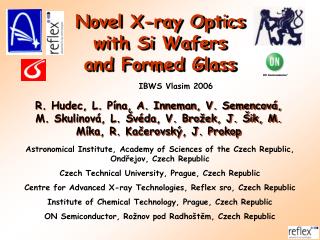
Novel X -ray O ptics with Si W afers and F ormed G lass. IBWS Vlasim 200 6. R. Hudec, L. P í na, A. Inneman, V. Semencov á, M. Skulinová, L. Švéda, V. Brožek, J. Šik, M. Míka, R. Kačerovský, J. Prokop.

E N D
Novel X-ray Optics with Si Wafers and Formed Glass IBWS Vlasim 2006 R. Hudec, L. Pína, A. Inneman, V. Semencová, M. Skulinová, L. Švéda, V. Brožek, J. Šik, M. Míka, R. Kačerovský, J. Prokop Astronomical Institute, Academy of Sciences of the Czech Republic, Ondřejov, Czech Republic Czech Technical University, Prague, Czech Republic Centre for Advanced X-ray Technologies, Reflex sro, Czech Republic Institute of Chemical Technology, Prague, Czech Republic ON Semiconductor, Rožnov pod Radhoštěm, Czech Republic
XEUS will have a very large collecting area and fine angular resolution of 2..5" so very light-weight novel X-ray optics is to be developed
Czech participation • ESA PECS project accepted for funding from Dec 2006, PI L. Pina Reflex, CI ASU, VSCHT, FJFI CVUT. Duration 4 years. • Preliminary results described in this talk were obtaained WITHOUT any funding thanks to the enthuniasmus of participants.
Our approach to X-ray optics based on Si wafers • the Si wafers parameters are optimized already at the production stage • the Si wafers are shaped to precise optical surfaces/shapes • the internal stress is minimized. Important. The standard Si wafers are not stress-free. • the shaped/bent Si wafers are stacked to form the Multi Foil Optics (MFO)
Measuring the quality of flatSi wafers • the production of Si wafers is a complex process. The recent Si wafers are optimized for semiconductor industry but not for X-ray optics applications • we use Si wafers already at production optimized for X-ray optics application • precise measurements and optimization already at production stage are important for X-ray optics based on Si wafers
Comparison of properties of Si wafers produced by different manufacturers CZ2 – ON Semiconductor Czech Republic MEMC – MEMC Electronic Materials SHE – Shin Etsu SEH WW – Wafers Works standard Si wafers
Thickness homogeneity of standard Si wafer produced by ON Semiconductor Czech Republic Flatness and thickness uniformity of a standard Si wafer (diameter 150 mm). Expected to further improve due to technological innovations planned.
6“ Silicon Wafer Manufacturing Process Flow Chart SINGLE CRYSTAL GROWING INGOT SHAPING EVALUATION FLATTING SLICING EDGE GRINDING LASER MARKING* LAPING AND CLEANING ACID ETCH ANNEALING* BACKSIDE TREATMENT* BACKSEAL OXIDE, POLYSILICON* New step:GRINDING POLISHING CHEMICAL CLEANING MECHANICAL CLEANING INSPECTION * Optional
Diamond Grinding Technology for Ideal Flatness Ground Si wafer TTV 0.37m
6“ Silicon Polished Wafer: Flatness Evolution (TTV) TTV <1m (2006) grinding technology TTV < 0.5 m (2007) new polisher (ordered) TTV < 2 m (2005) process optimization TTV = 1.68 m TTV = 0.76 m measured Total Thickness Variation
Measuring of shape Still optical profilometer – 3D chart flat Si wafer (dopant As), D = 150 mm, t = 0.625 mm Special very flat Si wafers have been developed in the collaborating industry for use in X-ray optics
Flat Si wafer, D = 150 mm, t = 0.625 mm ON Semiconductor Czech Republic, Taylor-Hobson profilometer, 2 perpendicular axes Flatness better than 1 mm
Flat Si wafer D=150 mm t=0.625 mm) ON SEMICONDUCTOR Measuring of microroughness AFM microscope, Ra ~ 0.1 nm in 10 x 10 mm
Measuring of roughness Interferometer Zygo, Ra ~ 0.2 nm in 1.4 x 1.1 mm dopant B, D = 150 mm, t = 0.625 mm ON Semiconductor, Czech Republic
Measuring of roughness Interferometer Zygo effect of various dopants on roughness (boron-B and phosphorus-P)
SHAPING OF SI WAFERS • the goal is to precisely shape Si wafers to desired optical shape and to remove the internal stress • 3 different technologies tested (I, II, III) • so far, Si wafers have been shaped to test cylindrical and parabolic surfaces both in 1 and in 2 dimensions
Si wafers shaping test cylindrical samplesgold-coated, D=100-150 mm, t=0.8-1.3 mm, R=1.5 m
Measuring of roughness after shaping Interferometer Zygo concave side convex side Bent (cylinder) Si wafer R = 1650 mm, D=150 mm, t = 1.3 mm
Measuring of shape Still optical profilometer – 3D chart flat Si wafer (dopant P) D = 150 mm t = 0.625 mm bent Si wafer (dopant P) D = 150 mm t = 1.3 mm R = 1650 mm
Deviation bent Si wafers before processing (deviation from plane) ± 2 µm after processing (deviation from cylinder) ± 2.5 µm
Parabolically shaped Si wafer, D = 150 mm, t = 0.625 mm profile measurement in 2 perpendicular axes
Measuring of shape Taylor-Hobson profilometer – deviation from ideal shape D = 150 mm, t = 0.625 mm, parabolic shape Except edge effects PV < 0.5 mm
Thermally formed Si wafers thermally formed Si wafer to test cylinder (R = 150 mm, 72 x 23 x 0.325 mm) thermally formed Si wafersto test cylinder (R = 150 mm, 50 x 7 x 0.625 mm)
Optimizing parameters of thermal forming of Si wafers The effect of elastic tension on deviation from ideal surface (thermal forming of Si wafers)
SUMMARY Si wafers • Interdisciplinary co-operation (team with 11 members from 5 Institutions) created within the Czech Republic with experienced teams including researchers at the large company producing Si wafers. • Si wafers successfully bent to desired geometry by 3 different techniques with PV ~ 1 mm in the best case. • The bending before stacking is advantageous eg. to avoid increase of internal stress and to allow very long-term stability of the mirror array. • The production of Si wafers very complex, need to modify and optimize the parameters at the production stage.
X-RAY OPTICS BASED ON GLASS THERMAL FORMING (GTF) alternative glass technologies represent glass forming avoiding heat
The parameters of the GTF may be improved by: • optimization of the glass material (limited) • optimization of the mandrel material/design • optimization of the GTF process • optimization of the GTF temperature and duration Expectations (goals) microroughness of float - glass not degraded ~ 0.5 nm RMS deviation PV < 0.02 mm
Various approaches in Glass Thermal Forming • low-cost design needed (the goal is to produce very large number of shells at a low cost) • expensive production/material are to be avoided • the mandrel material/design is important • recent design: proprietary technology(composite)
Glass Thermal Forming – one of studied approaches parabolic profile
Glass thermal forming (GTF) cylinder profile75 x 25 x 0.7 mm parabolic profile100 x 150 x 0.7 mm the largest samples so far 300 x 300 mm
Measuring float glass (flat glass substrates) used for GTF
Measuring of roughness before slumping Interferometer Zygo flat thin glass, 100 x 70 x 0.75 mm
Measuring of roughness after sluming Interferometer Zygo bent glass, R = 150 mm, 75 x 25 x 0.75 mm
Measuring of the roughness after slumping Interferometer Zygo, bent glass, 75 x 25 x 0.75 mm, optimization using > 100 samples formed at different conditions minimal value Optimizing the parameters of GTF Ra [nm] RMS[nm]
Waviness of the surface as function of time and temperature of GTF based on TH profilometer measurements of numerous samples (75 x 25 x 0.75 mm, R = 150 mm) - optimization
Measuring of shape Still optical profilometer – 3D chart thermally formed glass, parabolic profile R = 150 mm, 100 x 150 x 0.75 mm, PV from ideal shape ~ 0.7 mm in the best case recently
SUMMARYGTF • surface microroughness not degraded down to measuring accuracy ~ few 0.1 nm • profile deviations 0.7 µm (peak-valley) in the best case recently, expectations < 0.02 µm • sensitive to T and other parameters of the TGF process = need for optimization • sensitive to mandrel design / material / process => need for optimization
SUMMARY • Samples of test X-ray mirrors have been produced using novel technologies. • Shaped thin glass mirrors and Si mirrors have been successfully produced. • Both approaches show promising results justifying further efforts in these directions. We acknowledge collaboration with ON Semiconductor CR, Rožnov pod Radhoštěm, Optical Development Workshop of the AS CR Turnov, and TTS sro Prague Contact: rhudec@asu.cas.cz
The End