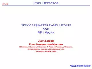
Patch Panel 1 (PP1)
Patch Panel 1 (PP1). Brief Review Cost and Effort Estimate. Patch Panel 1. TRT Forward. TRT Forward. SCT Barrel. Services and Beam Pipe Support Structure. Services and Beam Pipe Support Structure. Pixel Detector. Side C. Side A. PP1 Region Functions. Cooling connections


Patch Panel 1 (PP1)
E N D
Presentation Transcript
Patch Panel 1 (PP1) Brief Review Cost and Effort Estimate
Patch Panel 1 TRT Forward TRT Forward SCT Barrel Services and Beam Pipe Support Structure Services and Beam Pipe Support Structure Pixel Detector Side C Side A
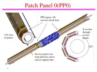
PP1 Region Functions • Cooling connections • Electrical connections • Optical fiber connections • N2 connections • Complete gas seal • Complete electrical shield PP1 Region <- Towards IP PP1b PP1a
PP1 Requirements • Provide cooling, electrical and fiber connections as specified in ATL-IP-ES-0007(“Pixel Services”) and described in ATL-IP-ES-0072. • Gas seal for 4 mbar maximum pressure differential consistent with 6 l/mbar-hour leak from the pixel volume. • Penetrations for cooling pipes to allow up to 3mm contraction from room temperature to cold temperature. • Access to beam pipe adjustment & allowance for beam pipe survey. • Cutouts for PST rails to allow pixel package insertion. • Outer diameter consistent with insertion of pixel package with PP1 attached to service panels • Electrical connection to PST and beam pipe EMI shields. • Temporary support of beam pipe during installation of the pixel package.
PP1 Endplate • Picture of prototype endplate. Machined aluminum, 6mm thick. Slots for fibers For cooling and gas connections Seal plates Slots for electrical feedthroughs For beampipe support and adjustment
Coolant Fittings • Lack of space, the need to allow contraction of the pipes and minimize forces on the endplate and the need for an electrical break requires us to use a custom fitting. PEEK insert electrical break PEEK seal to pipe Threaded insert into endplate Tube flared in place PEEK nut Bellows for contraction of pipes upon cooldown
More Coolant Connections • Commercial fittings at PP1b desired but not yet selected • Filter between PP1b and PP1a, also not selected. • Custom wrenches for PP1a are needed (under design). Space is very limited. • Same for PP1b? Not clear yet
Electrical Feedthroughs • Fabricated for simple functional tests and for mockup. • Connections to PP0(largely already made on prototype) • Thermal tests • HV isolation • Add PP1b connectors, read out real modules
Optical Fibers • Ericsson study of MT16 connectors with bare ribbons on the PP0 side and corresponding cables on the PP1a side. • Mechanical(glued) interface to PP1 endplate slot.
PP1 Prototype • Plan is to make enough coolant fittings for one quadrant. • Custom bellows ordered • Other parts either ready to order or sent to shops. • Would then assemble into quadrant of prototype endplate to get experience. • Current plan is to use paper(rad-hard and cheap) gaskets for seal. Will test this idea in small setup also after irradiation, in addition to full scale. • Would mount endplate as shown with coolant connections(and blanked off electrical and fiber connections) to measure leak rate attached to 30cm PST prototype with flanges. Repeat after adding electrical connections. • Fiber plan not yet clear – scope of Ericsson prototypes not likely to fill all of slot.
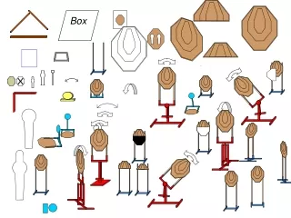
Mockup at CERN • Assembly started
Cost and Effort Estimate Included in estimate: • Bulkhead • Bulkhead seal ring and gasket • Bulkhead center support, bellows, connection to beam pipe • Coolant pipe feedthrus (supply and return) • Striplines • Corrugated support for PP1b electrical cable connectors • Full prototype of one PP1 quadrant • Contingency Not included in estimate (as they are in other cost estimates): • Fiber optic cables • PP1a fiber optic cable feedthrus • PP1a beam pipe adjusters • PP1a to PP1b coolant pipes • PP1b coolant pipe connectors • PP1a to PP1b electrical cables • PP1b electrical cable connectors • PP1b filter/pressure drop devices
Conclusion • Preliminary design of PP1 and related items well advanced. More work is needed to complete design. • Prototypes of critical components either fabricated or under fabrication. • 1-to-1 mockup assembly started at CERN • Next major steps are to complete quarter-scale prototype and to finish mockup studies. • Preliminary cost and effort estimate: • Total cost: $472K • Total effort: 27 FTE-months