Four Seasons April 24, 2008
740 likes | 950 Vues
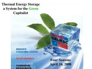
Thermal Energy Storage a System for the Green Capitalist. Four Seasons April 24, 2008. Agenda for Our Green Capitalist’s Discussion. What is TES or Off Peak Cooling? LEED and Why is Storage Green ? Storage Benefits Storage Myths Look what it does for the Building Load Profile

Four Seasons April 24, 2008
E N D
Presentation Transcript
Thermal Energy Storagea System for the Green Capitalist Four Seasons April 24, 2008
Agenda for Our Green Capitalist’s Discussion What is TES or Off Peak Cooling? LEED and Why is Storage Green? Storage Benefits Storage Myths Look what it does for the Building Load Profile How does OPC work? How does it Work With the Utility Rate? Conclusions
Off-Peak Cooling is growing for three reasons: • LEED, and sustainable designing. • Utility rates are becoming more favorable for storage. • Usually it’s the best design.
What is Off Peak Cooling? TES is the process of generating and storing cooling at night-time to: 1. Reduce peak daytime kW demand. 2. Reduce energy consumption. 3. Lower power plant emissions.
Most common TES System Electric Water Heater Assume one low flow showers running ((2.5gpm x 8.33 lb/gal x (110-60)) x 60 minutes/hr / 3,414 Btu/kWh = 18.3 kW each East Coast of US 100,000,000 people x 25% x 1/12 Hr/shower x 18.3 kW= 38 Gigawatts = CA Electric Peak on Summer day 4.5 kW Heater Gas Water Heater Design Load = 2 Showers at a time 18.3 kW x 2 x 3414 = 124,950 Btuh TES has already impacted US infrastructure
Speaking of INFRASTRUCTURE
Utility Load Factors* in the USA *Load Factor = Avg. Load Peak Load
One Metric for “Green” is LEED LEED™ Green Building Rating System
Credit Areas Comprise 69 Total Possible Points LEEDTM Credits Materials & Resources Water Efficiency Indoor Environmental Quality Sustainable Sites Energy & Atmosphere Sustainable Sites: 14 points Water Efficiency: 5 points Energy* & Atmosphere: 17 points Materials & Resources: 13 points Indoor Environment Quality: 15 points Innovation & Design: 5 points 69 points *10 Energy Credit are based on ASHRAE 90.1 which is based on Energy COST Reduction
Reduce design energy cost over ASHRAE 90.1, 2004 Energy Cost Budget, or your local code (which ever is more stringent). LEED EAc1 Point Awards 2 Credits will be mandatory in EA Prerequisite 2
Is Off Peak Cooling Green? Can Off Peak Cooling Save Energy? General perception is that: Thermal Storage uses more energy and is notGreen
Storage is Green Because… • Storage greatly reduces Energy Costs • May Save Energy at Site • Always Saves Energy at the Source of Generation • Lowers Power Plant Emissions
Off-Peak Cooling is Green Because… • Storage saves energy because: • Base Load Plants 7900 to 8500 Btu/kW • Peaking Plants 9000 to 12000 Btu/kW • Spinning Reserve Losses • More Efficient Nighttime Transmission • Last Plant On- Twice As Dirty as First On
LEED points awarded on COST REDUCTION • LEED ignores the utility meter • LEED reads the utility bill • Meters don’t measure energy • ASHRAE 90.1, 1999 • Energy Cost Budget Method
Thermal Energy Storage Benefits Reduces Peak Demand at most critical time 20-40% Reduces first cost (sometimes) up to 10% Reduces consumer’s AC energy costs 10-20% Reduces on site energy use (often) up to 14% Reduces source energy usage (always) 8-34% Increases Load Factor of Generation up to 25% Reduces TEWI emissions 30 to 50% vs. Absorption Provides operational flexibility for consumer in a deregulated energy market
Thermal Storage Myths • 1. Uncommon • 2. Too Much Space • 3. Too Complicated • 4. Doesn’t Save Energy • 5. Too Expensive • 6. Lack of Redundancy (Risky) • Rates Will Change • Modeling Doesn’t Show Results
Look What Storage Does: For Your Building And For the Energy Provider
ASHRAE 90.1 Base Line BuildingNon-Storage Electrical Profile Peak Load 2000 kW Avg. Load 1050 kW 6 am Noon 6 pm (Load Factor = 53%) Total kWh = 28,000/day
Avg. Load 800 kW Design 30% better than 90.1Non Storage Electrical Profile Peak Load 1500 kW 6 am Noon 6 pm (Load Factor = 53%) Total kWh = 19,200/day
600 kW Shed Peak Load 900kW Ice Making Ice Making Off Peak Cooling (OPC) Electrical Profile 40% Peak Load Reduction Avg. Load 800kW 6 am Noon 6 pm (Load Factor = 88%) Total kWh = 19,200/day
Generator Load Factor 4 Buildings x 1 Megawatt = 4 Megawatts 8,000 mW-h Sold 5 Buildings with TES @ 0.8 mW = 4 Megawatts 10,000 mW-h Sold! The same generator produces 25% more sellable kW-h!
Higher Load Factors Yield Lower Energy Bills The first law of electricity pricing: “Load Factor IS The Only Factor”
What’s your load factor? Load Factor = _____Total kWh____ Peak kW x 720 Hours
Prospecting Guide • Is the job chilled water? • Is the job over 100 tons? • Is there time to make ice? • Is this a LEED design?
What job types are best? NewConstruction or NewChiller Plants BEST
What about retrofit? They’re good but need Opportunity for avoided capital cost Best When: Replacing old chillers Capacity increase required Operating savings alone NEVER JUSTIFY STORAGE.
What building types are best? • K-12 Schools • Community Colleges • Arenas, Theaters, Conference Centers • Office Buildings • Libraries • Churches • Solving Redundancy and Infrastructure Issues
Myth: Storage is Complicated True or False ?
Simple System…….. Almost like Non-Storage System Control Logic Chiller Based System No Refrigeration Piping Closed System Coolant fluid is not storage media Heat Transfer Fluid So what is “Different”? Two Valves Two Bypasses Storage Tanks
Thermal Storage Tank Expansion Chamber Seamless Polyethylene Tank Polystyrene Insulation All Welded Polyethylene Heat Exchanger
INTERNAL HEAT EXCHANGER 14,000 FT OF HX TUBING FUSION WELDED POLYETHYLENE TUBING CORROSION PROOF PREDICTABLE & REPEATABLE PERFORMANCE 100% SERVICEABLE SIMPLE FLANGE CONNECTIONS
SERIES FLOW – CHILLER UPSTREAM Back Pressure BASIC DIAGRAM RegulatingValve CHILLER P1 V1 V2 AirHandlers P2 ICE BANK
SERIES FLOW – CHILLER UPSTREAM Back Pressure CHARGING, and WITH COOLING RegulatingValve CHILLER P1 58F 26F-22F V1 V2 AirHandlers 32-28F P2 ICE BANK 42F
SERIES FLOW – CHILLER UPSTREAM Back Pressure COOLING CHILLER ONLY RegulatingValve 42F-58F CHILLER P1 58F 42F-50F V1 42F V2 AirHandlers P2 ICE BANK 42F
SERIES FLOW – CHILLER UPSTREAM Back Pressure COOLING CHILLER and ICE RegulatingValve 42F-58F CHILLER P1 58F 42F-50F V1 42F V2 AirHandlers 32F-42F P2 ICE BANK 42F
SERIES FLOW – CHILLER UPSTREAM Back Pressure COOLING ICE ONLY RegulatingValve 42F-58F CHILLER P1 58F 42F-58F V1 42F V2 AirHandlers 32F-42F P2 ICE BANK 42F
SERIES FLOW – CHILLER UPSTREAM EQUIPMENT SCHEDULE Regulating Valve CHILLER P1 V1 A V2 A C B C B AirHandlers P2 ICE BANK
AIR SUPPLY/PRESSURE SENSING TUBE INVENTORY METER TANK COVER CHARGED WATER LEVEL WATER EXPANSION AREA 6” DISCHARGED WATER LEVEL HX TUBING INSULATION LAYER
Ice Inventory Meter Model LL-102
Would need 25% of roof space on 100 story building! How Much Space? • 0.70% of cooled floor space* • If Ice provides about 33% of a cooling system reducing ice tank floor space to 0.23% of cooled floor space. 1 ton cools 500 ft2 1 tank provides 20 tons 1 tank cools 10,000 ft2 1 tank needs 70 ft2 (60 ft2 ) Same ratio as the water heater in your house