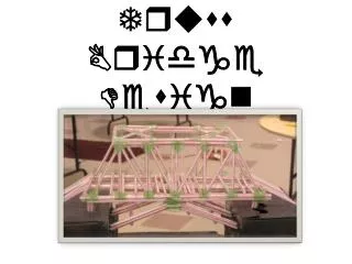
The truss lesson
The truss lesson. f or people that are pretty smart. For your reference throughout the lesson:. pin. member. wall. j oint. roller. Force notation examples: F R B = reaction force exerted by joint B F A AC = force applied to member AC F A x = force applied to object in x direction


The truss lesson
E N D
Presentation Transcript
The truss lesson for people that are pretty smart
For your reference throughout the lesson: pin member wall joint roller Force notation examples: FRB = reaction force exerted by joint B FAAC = force applied to member AC FAx = force applied to object in x direction FRy = reaction force exerted by object in y direction Force variables refer to the magnitude of the vector (a positive number, not the signed force) Direction symbols: ⊥ = perpendicular (-) = negative (+) = positive (⟳) = clockwise (⟲) = counterclockwise
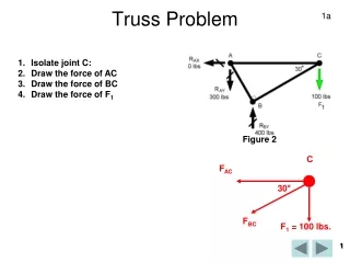
Problem:Determine the forces on each joint and member. C y’ f lbs θ˚ A B x’
Steps ① ∑m = 0 = mA + mR ② ∑Fx = 0 = FAx + FRx ∑Fy = 0 = FAy + FRy ③ (Same as 2) for each joint ④ Determine tension or compression For the entire structure
Step 1: Σm = 0 (balance the moments on the structure) m = Torque/Moment (Angular force) Think of torque as a force trying to rotate an object about a point P. Moment is measured in ft-lbs. To calculate angular force, use m = r ∙ F where r is the radius (distance to point P) ⊥ to F, the linear force F F pretend it’s up here r P P r the applied force the applied force To find r, imagine rotating F around P so it is ⊥ to the object or member Imagine rotating the object around P so it is ⊥ to F OR
Step 1.1 calculate applied torque/moment To find mA (the applied moment), “rotate” AC until the force is ⊥. r, or the distance to the fulcrum C, is x feet. mA = r ∙ F = x ∙ f = fx ft-lbs Direction: (⟳) clockwise or (-) This is the torque on the whole structure, about the fixed pin at C. Step 1.2 calculate reaction moment So fx ft-lbs are acting on the structure. To calculate the reaction to this, Use ∑m = 0 = mA+ mR action reaction 0 = mR – fx mA is made (-) because it is (⟳) mR = fx (⟲) f x’ C B A action C reaction A B
Step 1.3 find the receiver of the reaction force We know that the initial applied force, mA, is exerted on point A. On what point is the reaction force exerted? Consider the force on A. It is clockwise, or acting in the negative direction. The only object in the negative direction of A linearly is the member AB, which is in the (-) x direction. The reaction force cannot originate in AB, however, because AB is not fixed. Because AB can only exert force in the x direction, we know the mA force is then exerted straight in the negative x direction, onto joint B. Joint B cannot push back, because it is not fixed. So point B continues to push in the negative x direction into the wall. We know the wall is fixed, so it is the source of the reaction force, and it exerts this force on the point B to counteract the applied moment. C action reaction A B
Step 1.4 convert reaction moment back to linear force We now know that mR = fx ft-lbs is acting on joint B. What is the linear reaction force exerted on B? Start with the moment equation: mR = r ∙ F from step 1.2 we know mR = fx ft-lbs fx ft ∙ 1 lbs = r ∙ F To find r, remember that the moment forces are acting on the structure about the fulcrum C. The reaction force is already ⊥ to the member BC, so the radius is simply the measure of BC, which is y ft. fx ft ∙ 1 lbs = y ft ∙ F the ft units cancel fx/y lbs = F the linear force on B (+), x C f lbs fx/y lbs A B
Step 2: ∑Fx = 0 , ∑Fy = 0 (balance x and y forces on entire structure using a global free body diagram) Applied/action forces (exerted on objects) Reaction forces (exerted by objects) Member forces Component forces of angled vectors C A B Look at the whole structure and assign forces to the joints, drawing arrows. (see next slide)
Rules for drawing arrows ① Applied Forces Draw the force where it is applied initially (A). Then draw the mR reaction force on the roller (this is considered an applied force because it acts on B and is exerted by the wall rather than any object in the structure). Because the size and position of the arrows don’t matter for now, you can draw the applied forces so that they won’t overlap with members or components of other vectors. ② Reaction Forces The pin exerts the global reaction forces. (Mr. Kaluta spent a long time in class explaining why this is. If you don’t get it, just trust me.) Draw in the x and y directions, opposite the applied forces. ③ Member Forces At each joint, draw an arrow for each of the connected members. As a default, draw these arrows in tension (away from joints). This can be changed later (if an answer comes out negative, it means the arrow’s direction should be switched). ④ Component Forces Draw x & y components for each angled arrow.
Step 3: ∑Fx = 0 , ∑Fy = 0 (balance x and y forces on each joint using localfree body diagrams) 3.1 Roller (B) transfer arrows from Global FBD Known: FAx = applied/action force = fx/y Balance & satisfy the equilibrium equations: ∑Fx = 0 = FAx + FRx 0 = fx/y + FRx FRx= –fx/y negative answer; change direction of FRx. ∑Fy = 0 = FBC no force exists to counteract the y force change the FRx direction and type (to a reactionary force) before FAx FRx B 0 after fx/y fx/y B
Something to remember before we continue:The arrows you draw are purely conceptual. If you think too hard about them, you will realize that the source of the force doesn’t really matter, as objects can exert both pushing and pulling forces, and any push or pull will have an opposite and equal reaction force. However, because we are using the joint method, we are interested in the forces involving the joints. For our purposes, at the beginning of each step all previously calculated forces are considered applied forces, acting on the joints. The reaction forces, which we consider to be exerted by the joints, are then calculated to balance the applied forces.Keeping that in mind… 3.15 Put the new arrows in context. Every joint and member must have a net force of zero, so AB must react to the force exerted on it by B. Based on this you can determine the direction of the x force exerted by AB on A, and its magnitude (equal to FRB). Understand that FRAB could be calculated using equilibrium equations, but they would be quite simple as a member can only push/pull in one direction. This step is simply used to determine the x force on A. Do it in your head and don’t over think it. FRB FRAB B A FAAB
reaction force FRAC and its components, FRxand FRy FAx direction found in step 3.15, changed from the global FBD before 3.2 (A) Known: FAx= FRAB= FRB = fx/y, FAy= f ∑Fx = 0 = FAx + FRx 0 = fx/y – FRx FRx made (-) because arrow points left FRx = fx/y ∑Fy = 0 = FAy + FRy 0 = FRy – f FAy made (-) because arrow points down FRy= f Because both FRx and FRycame out positive,FRAC is in the right direction • Find FRACby solving one of the following equations: • FRx= f = FRAC sinθ FRy= fx/y = FRAC cos θ FRAC = √ (FRy)2 + (FRx)2 • (trig) (trig) (pythagorean) • Though the pythagorean method can be used in this case, you may have to use one of the trig equations in another problem. • Note the result of this step, at right. θ˚ FAx A FAy f / sinθ fx/y A after f
Note: the BC member force has been removed because step 3.1 found it was 0. • Known: FA = f/sinθ (found by one of 3 equations in 3.2) • Simple trig can be done to find that FAx and FAy • are equal to the components from joint A. • FAx= fx/y, FAy = f • ∑Fx = 0 = FAx + FRx • 0 = fx/y – FRx FRx made (-) because arrow points left • FRx = fx/y • ∑Fy = 0 = FAy + FRy • 0 = FRy – f FAy made (-) because arrow points down • FRy= f • Again, both are positive, and therefore these arrows are in the correct directions. 3.3 (C) FRy C FRx FAx FA FAy
Step 4: Find tension & compression Tension and Compression refer to the direction of the forces exerted by members or joints (reaction forces). Tension – the member or joint is exerting outwards from itself (push) Compression – the member or joint is exerting inwards, towards itself (pull) Put all non-zero member forces on the diagram. B is pulling in along AB. Compression. A is pulling in along AB. Compression. AB reacts to these forces by pulling in. Compression. BC is under 0 force. C is pushing out along AC. Tension. A is pushing out along AC. Tension. AC reacts by pushing out. Tension. Therefore AC is a string under tension and AB is a stick under compression. C A B
ANSWER. f fx/y C f/sinθ f/sinθ lbs of tension* 0 lbs f lbs f/sinθ fx/y A fx/y B fx/y lbs of compression* * I am not sure if these should be doubled. Anyone know? Also, I used f, x, y, and θ just to make this a general case. I do not recommend using these answers as formulas.
Questions, Comments, Corrections, Suggestions Please view this Google Doc (you don’t need a Google Docs account to view and edit) Printable Version Click hereto download a pretty printable version of the lesson. You can edit before you print out.