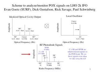
Precision Optical Frequency Locking System Using Microcavity Discharge for Neon Tuning
This project aims to develop a high-precision optical frequency locking system to tune a diode laser to an atomic transition in Neon. The system utilizes a microcavity discharge device, which offers advantages such as reduced size, higher integration potential in silicon, and greater species density for increased opto-galvanic response. As telecom channel spacings decrease, reliable ultra-accurate frequency sources are essential for expanded bandwidth and all-optical network monitoring. Components include a tunable red diode laser, detection circuitry, and a specialized microcavity device for enhanced sensitivity and stability.

Precision Optical Frequency Locking System Using Microcavity Discharge for Neon Tuning
E N D
Presentation Transcript
Optical Frequency Locker Scott McCain in conjunction with the Optical Physics and Engineering Lab
Objective of System • To build a system to tune a diode laser to an atomic transition in Neon to a very high precision using a microcavity discharge device operating as a hollow cathode.
Why build a wavelength locker? • Optical telecom channel spacing is becoming smaller than the resolution of conventionalal optical spectrum analyzers • Stable, ultra-accurate frequency sources will be needed to increase bandwidth • All-optical monitoring of networks can be achieved with accurate frequency references
Advantages of Microcavity Device • Current research in atomic transition-based tuning has been centered on conventional hollow cathode lamps • Microcavity devices offer the advantages of smaller size, possibility of integration in silicon, and greater densities of species thus greater opto-galvonic response
Overview of System • A tunable, red diode laser is used as the frequency source • A Neon-filled microcavity device is used to detect when the diode laser is at a specific frequency by measuring the opto-galvonic effect • The diode laser is tuned to the desired frequency by adjusting the current and temperature until a strong opto-galvonic response is measured
System Components • Microcavity Device • Laser Diode and Controls • Modulation and Detection Components
Microcavity Structure-Side View Glass Enclosure 420 um To Vacuum Sys Anode Conductor Insulator 1 mm Conductor .5 mm Cathode
Microcavity Construction • Devices made from ceramic and aluminum • Holes were drilled using either a drill bit, ultra-sonic mill, or laser drill through conductor and insulator • Large holes were used (~300-400 um) to make focusing the diode easier • Ceramic and aluminum were glued together using torr seal, a glue that doesn’t outgas in a vacuum system • Test tubes, microscope slides, and small tubes were cut and torr sealed to seal the device
Microcavity Filling • The device was then put into a vacuum system via the small tube that was glued on • With roughing pumps and turbo pumps, the device was pumped down to a very low pressure to eliminate most contaminants (~1e-7 Torr, 1 atm=760 Torr) • The device was then filled with ~100 T of Neon
Operation of the Microcavity Device • A high voltage power supply with a 500 kΩ resistor in series was hooked up to the device • Device would initiate gas discharge at ~400-500 V with ~.3 mA of current
Diode Laser Relevant Laser Diode Characteristics • Small and inexpensive • Available in many different frequencies • Frequency tunable by temperature and drive current • Bad beam characteristics- diverges and is elliptical
Selection of Diode Laser • Need a frequency range that includes a strong atomic transition in Neon • NIST Atomic Spectra Database was used to find a strong Neon transition in visible red • A 635 nm laser was chosen because DVD players use this wavelength so the diodes are readily available and inexpensive and Neon has a strong transition at 633.4 nm
Tuning of Diode Laser • Laser diode center wavelength heavily dependent on current and temperature • A peltier cooler was chosen because it can cool or heat diodes very effectively • A thermistor was used to monitor the temperature (a thermistor is basically a resistor with high temperature variation) • A ILX-Lightwave Laser Diode Driver was used to control the temperature and current of the diode • A .2 nm resolution OSA was used to gather preliminary data for the diode
Focusing of Diode Laser • High power lens with focal length of ~1 mm and a 3-d precision stage was used to focus the diode beam
Opto-Galvonic Effect • The phenomenon by which a gas discharge changes impedance when enough radiation at a frequency corresponding to a strong atomic transition in the gas is incident upon it • Related to changes in the population distribution of the gas and higher ionization probabilities of excited states
Modulation and Detection of the Diode Laser • Initial plans of tuning the laser and watching for the opto-galvonic response on a voltmeter were unsuccessful, the signal was too noisy • A chopper and lock-in amplifier were added to aid in detecting the signal • A chopper is a fan with evenly spaced holes that can have its frequency tightly controlled, when put in front of the laser diode it essentially modulates the beam with a square wave at the frequency of the fan openings • A lock-in amplifier picks out a signal at a desired frequency from a mess of signals and amplifies it
Detection Circuitry Anode HV Power Supply + - Cathode Diode Ctls Chopper @ 1kHz Discharge Device 500 kΩ Lock-in Amp Tuned To 1 kHz Bandpass Filter @ 1 kHz 5 kΩ
Signal Detection • Excessive noise was on the input signal to the lock-in amplifier even after many attempts to filter it • With the excessive noise, I wasn’t able to have very good sensitivity on the detection of the signal and only detected noise
Lessons Learned • A more stable material system for the microcavity device should be used, further attempts at silicon devices should be explored • Sealing the devices from the vacuum system introduces contaminants and the devices only last a few hours, better ways of sealing them should be investigated • A better scheme for modulating the laser should be used, possibly by modulating the laser current with a dc signal and a small signal sinusoid to better match the frequency instead of varying the current via the diode controller