Architectural Modeling Notations
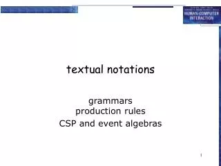
Architectural Modeling Notations. Objectives. To present several notations for architectural modeling Box-and-line diagrams UML package diagrams UML component diagrams UML deployment diagrams To present UML common notations Notes Constraints Properties Stereotypes. Topics.

Architectural Modeling Notations
E N D
Presentation Transcript
Objectives • To present several notations for architectural modeling • Box-and-line diagrams • UML package diagrams • UML component diagrams • UML deployment diagrams • To present UML common notations • Notes • Constraints • Properties • Stereotypes
Topics • Box-and-line diagrams • UML common notations • Packages and package diagrams • Components and component diagrams • Nodes, artifacts, and deployment diagrams
Box-and-Line Diagrams • Icons (boxes) connected with lines • No rules governing formation • Used for both static and dynamic modeling • Good idea to include a legend
Box-and-Line Diagram Heuristics • Make box-and-line diagrams only when no standard notation is adequate. • Keep the boxes and lines simple. • Make symbols for different things look different. • Use symbols consistently in different diagrams. • Use grammatical conventions to name elements. • Don’t mix static and dynamic elements.
UML Notes and Constraints • Note—A dog-eared box connected to model elements by a dashed line • May contain arbitrary text • Used for comments and specifications • Constraint—A statement that must be true of entities designated by model elements • Written inside curly brackets • Beside single model elements • Beside a dashed line connecting several model elements
UML Properties and Stereotypes • Property—Characteristic of an entity designated by a model element • List of tagged values in curly brackets • Tagged value: tag = value • Boolean properties that are true may drop the value and equals sign • Stereotype—A model element given more specific meaning • Shown with icons, colors, graphics • Stereotype keywords between guillemots, for example «interface»
UML Dependency Relations • Examples: D uses I, D depends for compilation on I, D imports I • Represented by dependency arrows: stereotyped dashed arrows A dependency relation holds between two entities D and I when a change in I (the independent entity) may affect D (the dependent entity).
UML Packages • A UML package is a collection of model elements, called package members. • The package symbol is a file folder • Package name in tab if body is occupied, otherwise in the body • Members shown in body or using a containment symbol (circled plus sign) • Often connected by import or export dependency arrows
Package Diagrams • A UML package diagram is one whose primary symbols are package symbols. • Useful for • Static models of modules, their parts, and their relationships • Architectural modeling
Software Components • A software component is a reusable, replaceable piece of software. • Component-based development is an approach in which products are designed and built using commercially available or custom-built software components.
UML Component Diagrams • A UML component is a modular, replaceable unit with well-defined interfaces. • Component symbols are rectangles containing names • Stereotyped «component» or have component symbol in upper right-hand corner • A UML component diagram shows components, their relationships to their environment, and their internal structure.
UML Interfaces • A UML interface is a named collection of public attributes and abstract operations. • Represented by a stereotyped class symbol (later) • Represented by special ball and socket symbols • Note: this use of the term “interface” is different from out previous use as a communications boundary.
Provided and Required Interfaces • A class or component realizes an interface when it includes its attributes and implements its operations. • Providedinterface—Realized by a class or component • Represented by a ball or lollipop symbol • Requiredinterface—Needed by a class or component • Represented by a socket symbol • The assembly connector wires interfaces together.
Component Internal Structure • Components can contain other components or classes showing how they are built. • A delegation connector ties a component interface to one or more internal classes or components that realize or use the interface. • Solid arrows • Stereotyped with «delegate»
Component Diagram Uses • Static models of software components (reusable and replaceable parts) • Model program components • Architectural models • Detailed design models • Relationship to environment • Model internal structure of components
Logical and Physical Architecture • Logicalarchitecture—The configuration of a product’s major parts and their relationships in abstraction from implementation as code on a real machine • Physicalarchitecture—The realization of a product as code and data files residing and executing on computational resources • UML deployment diagrams model physical architecture.
UML Artifacts • A UML artifact is any physical representation of data used or produced during development or operation. • Examples: Files, documents, program code • Artifacts have types and instances • Represented by rectangles containing names • Stereotyped «artifact» or have artifact symbol in upper right-hand corner • Instances have underlined names, types do not • Artifacts realize logical entities (classes, components, etc.)
UML Nodes • A UML node is a computational resource. • Device—A physical processing unit, such as a computer • Executionenvironment—A software system that implements a virtual machine, such as an operating system or language interpreter • Represented in UML by box or slab symbols • Stereotyped with «device» or «execution environment» • Types and instances • Types have names • Instance have underlined labels of the form name : type • Name or type may be suppressed, but not both
Deployment Diagrams • A UML deployment diagram models computational resources, communication paths among them, and artifacts that reside and execute on them. • Used to show • Real and virtual machines used in a system • Communication paths between machines • Program and data files realizing the system • Residence • Execution
Deployment Diagram Rules • Computational resources are nodes • Communication paths are solid lines between nodes • May be labeled • May have multiplicities and role names • Artifact symbols may • Appear within node symbols • Be listed within node symbols • Be connected to node symbols by dependency arrows stereotyped with «deploy»
Summary • Box-and-line diagrams are used to make static and dynamic architectural models. • Notes, constraints, properties, and stereotypes can be used in any UML diagram. • Package diagrams are used to model modules and their parts. • Component diagrams are used to model software components. • Deployment diagrams are used to model physical architectures.