BLDC MOTOR SPEED CONTROL USING EMBEDDED PROCESSOR
BLDC MOTOR SPEED CONTROL USING EMBEDDED PROCESSOR. PROJECT BY K. JEBASTIN S. RAMESH D.REUBEN DEVASIGAMANI M. SATHISH KUMAR. INTRODUCTION. In this project, we are going to control the speed of the DC motor using Embedded processor. HARDWARE USED. LPC-2138 microcontroller, ARM processor,

BLDC MOTOR SPEED CONTROL USING EMBEDDED PROCESSOR
E N D
Presentation Transcript
BLDC MOTOR SPEED CONTROL USING EMBEDDED PROCESSOR PROJECT BY K. JEBASTIN S. RAMESH D.REUBEN DEVASIGAMANI M. SATHISH KUMAR
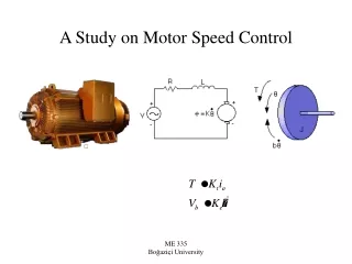
INTRODUCTION • In this project, we are going to control the speed of the DC motor using Embedded processor.
HARDWARE USED • LPC-2138 microcontroller, • ARM processor, • Driver circuit for motor, • DC motor.
SOFTWARE USED • Embedded “C” language programming. • KEIL micro vision 3 for ARM programming.
FEATURES OF MICROCONTROLLER • n 16/32-bit ARM7TDMI-S microcontroller in a tiny LQFP64 package. • n 8/16/32 kB of on-chip static RAM and 64/512 kB of on-chip Flash program memory. • 128 bit wide interface/accelerator enables high speed 60 MHz operation. • n In-System/In-Application Programming (ISP/IAP) via on-chip boot-loader software. • Single Flash sector or full chip erase in 400 ms and programming of 256 bytes in 1 ms. • n EmbeddedICE® RT and Embedded Trace interfaces offer real-time debugging with the • on-chip Real Monitor™ software and high speed tracing of instruction execution. • n One (LPC2131/2132) or two (LPC2138) 8 channel 10-bit A/D converters provides a total of up to 16 analog inputs, with conversion times as low as 2.44 ms per channel. • n Single 10-bit D/A converter provides variable analog output. (LPC2132/2138 only) • n Two 32-bit timers/counters (with four capture and four compare channels each), PWM • n Real-time clock equipped with independent power and clock supply permitting • extremely low power consumption in power-save mode. • n Multiple serial interfaces including two UARTs (16C550), two Fast I2C-bus (400 kbit/s),
n Up to 47.5 V tolerant general purpose I/O pins in tiny LQFP64 package. • n Up to nine edge or level sensitive external interrupt pins available. • n 60 MHz maximum CPU clock available from programmable on-chip PLL with settling time of 100 ms. • n On-chip crystal oscillator with an operating range of 1 MHz to 30 MHz. • n Power saving modes include Idle and Power-down. • n Individual enable/disable of peripheral functions as well as peripheral clock scaling down for additional power optimization. • n Processor wake-up from Power-down mode via external interrupt. • u CPU operating voltage range of 3.0 V to 3.6 V (3.3 V ± 10 %) with 5 V tolerant I/O pads.