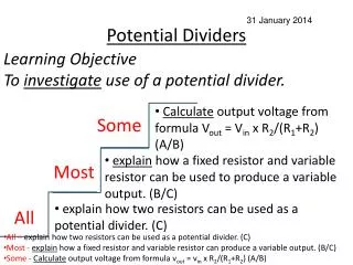
Potential Dividers
Potential Dividers. You will be familiar with the use of a variable resistor to vary current. M. The variable resistor acts as a control over the flow of current. It is being used as a rheostat. The result is a control over the speed of the motor. more resistance.

Potential Dividers
E N D
Presentation Transcript
Potential Dividers You will be familiar with the use of a variable resistor to vary current.
M The variable resistor acts as a control over the flow of current. It is being used as a rheostat. The result is a control over the speed of the motor. • more resistance The next circuit is very different.. • less current • slower motor
R1 V V1 R2 V2 V does not change V = V1 + V2 The two resistors are dividing up the potential (or voltage) - (the Potential Divider)
What happens if: V1 V V2 R1 increases and R2 is unchanged? V R1 decreases and R2 remains the same? V The values of both R1 and R2 are doubled? V1 V V2 The values of both R1 and R2 are halved? V1 V V2 The supply voltage V is trebled? x 3 x 3 3V
Uses of the potential divider • To supply a variable voltage • To make an input sensor from other components - many detectors will switch on as a voltage goes above or below a certain threshold (such as in a thermostat).
R1 V V1 R2 V2 Consider the thermistor -its resistance decreases as the temperature increases R1 is a thermistor. Suppose a heater switches on if V2 “went high”. decreases As it gets hot, R1xxcreases and so V1xxxxs. Falls This means V2 must xxxx. ie it “goes ?” Rise The thermostat turns on. Could you explain what would happen if you put the thermistor where R2 is?
R1 V V1 R2 V2 Now using the original circuit as in the diagram, what would be the effect of making R2 a variable resistor? It would effectively vary the switching temperature.
An LDR (light dependent resistor) has a resistance which decreases with increased illumination. Sketch a circuit to show how you could use a power supply, voltmeter, LDR and a fixed resistor to measure light intensities. What would be the point in replacing the fixed resistor with a variable resistor? How would you modify your circuit to measure temperature instead of light intensity?
R1 V V1 R2 V2 Replace with an LDR
What would be the point in replacing the fixed resistor with a variable resistor? Change the lighting level at which it switched How would you modify your circuit to measure temperature instead of light intensity? Use a thermistor
2 volt A B S V Measuring PD with a potential divider. If AS was 25cm, what would the voltmeter read? 2Vx(25cm/100cm) = 0.5V Moving the slider S from A to B will make the voltmeter read from zero up to the supply voltage - in this case from 0V to 2V. If SB was 20cm, what would the voltmeter read? 2V((100cm-20cm)/100cm) = 1.6V We don’t really need the voltmeter to know what that voltage is! The resistance AB could be 1m of “resistance wire”.
2 volt A B Centre Zero galvanometer - a very sensitive ammeter. S V We don’t really need the voltmeter to know what that voltage is! This is only because the current through the wire AB is the same along its length and we assume none flows through the voltmeter. For practical purposes a resistor is frequently placed in series with the galvo to protect it from high currents.
2 volt A B Centre Zero galvanometer - a very sensitive ammeter. S V • Suppose the voltage from A to S is the same as the emf of the second cell. • The voltage drop from A to S due to the 2 V cell will match the emf from the other cell so no current will flow through the galvo. • If we move S to the left, VAS falls, so V will drive current through the galvo. • If we move S to the right, VAS rises and forces current back through the galvo and cell, the other way. • We now know that V = VAS.
Question If the wire AB is 1m long and a “balance point” is reached when AS = 20cm, What is the value of V ? V = 2volt x (20cm/100cm) V = 0.4volt
Why might you do the following? Add this resistor here? 2 volt A B S V 2 volt A B S V Add this switch and resistor here? This type of circuit is frequently used to measure very small emfs such as those generated by thermocouples - what are they? It is called a null method as a reading is made when the galvo is reading zero. It is more accurate to look for the balance point when making the connection at S produces no deflection of the galvo - why?