Operating System 11 I/O MANAGEMENT AND DISK SCHEDULING
550 likes | 1k Vues
Operating System 11 I/O MANAGEMENT AND DISK SCHEDULING. I/O DEVICES. Categories: • > Human readable: Suitable for communicating with the computer user. Examples : include printers and terminals, the latter consisting of video display, keyboard, and perhaps other devices such as a mouse.

Operating System 11 I/O MANAGEMENT AND DISK SCHEDULING
E N D
Presentation Transcript
Categories: • •> Human readable: Suitable for communicating with the computer user. Examples :include printers and terminals, the latter consisting of video display, keyboard,and perhaps other devices such as amouse. • •> Machine readable: Suitable for communicating with electronicequipment.Examples are disk drives, USB keys, sensors, controllers,and actuators. • •> Communication: Suitable for communicating with remote devices. Examples are digital line drivers and modems. • There are great differences across classes and even substantialdifferenceswithin each class. Among the key differences are the following: • • Data rate • Application • Complexity of control • Complexity of control • Data representation • Error conditions
•Programmed I/O:The processor issues an I/O command, on behalf of a process, to an I/O module; that process then busy waits for the operation to be completed before proceeding. • Interrupt-driven I/O: The processor issues an I/O command on behalf of a process. There are then two possibilities. If the I/O instruction from the processis nonblocking, then the processor continues to execute instructions from theprocess that issued the I/O command. If the I/O instruction is blocking, thenthe next instruction that the processor executes is from the OS, which will putthe current process in a blocked state and schedule another process. • Direct memory access (DMA): A DMA module controls the exchange of data between main memory and an I/O module. The processor sends a request forthe transfer of a block of data to the DMA module and isinterrupted onlyafter the entire block has been transferred.
The Evolution of the I/O Function • The evolutionary steps can be summarized as follows: • The processor directly controls a peripheral device • A controller or I/O module is added.The processor uses programmed I/O without interrupts. • The same configuration as step 2 is used, but now interrupts are employed.Theprocessor need not spend time waiting for an I/O operation to be performed, thus increasing efficiency. • The I/O module is given direct control of memory via DMA. • The I/O module is enhanced to become a separate processor, with a specializedinstruction set tailored for I/O.The central processing unit (CPU) directs the I/Oprocessor to execute an I/O program in main memory • The I/O module has a local memory of its own and is, in fact, a computer in its own right
Direct Memory Access • > The DMA unit is capable ofmimicking the processor and, indeed, of taking over control of the system bus justlike a processor. It needs to do this to transfer data to and from memory over the system bus. • > TheDMAtechnique works asfollows.When the processor wishes to read orwrite a block of data, it issues a command to the DMA module by sending to theDMA module the information
Design Objectives • Two objectives are paramount in designing the I/O facility: efficiency and generality.Efficiency is important because I/O operations often form a bottleneck in a computing system. • Swapping is used to bring in additional ready processes to keep the processor busy, but this in itself is anI/O operation.Thus, a major effort in I/O design has been schemes for improving theefficiency of the I/O.The area that has received the most attention, because of its importance,is disk I/O, and much of this chapter will be devoted to a study of disk I/O efficiency. • The other major objective is generality. In the interests of simplicity and freedomfrom error, it is desirable to handle all devices in a uniform manner.This statementapplies both to the way in which processes view I/O devices and the way inwhich the operating system manages I/O devices and operations.
The details of the organization will depend on the type of device and theapplication. The three mostimportant logical structures are presented in the figure.Of course, a particular operatingsystem may not conform exactly to these structures.However, the general principlesare valid, and most operating systems approach I/O in approximately this way.Let us consider the simplest case first, that of a local peripheral device thatcommunicates in a simple fashion, such as a stream of bytes or records. The following layers are involved: • • Logical I/O: The logical I/O module deals with the device as a logical resourceand is not concerned with the details of actually controlling the device. • • Device I/O:The requested operations and data (buffered characters, records,etc.) are converted into appropriate sequences of I/O instructions, channelcommands,and controller orders. • • Scheduling and control: The actual queuing and scheduling of I/O operationsoccurs at this layer, as well as the control of theoperations.Thus, interrupts arehandledat this layer and I/O status iscollected and reported.This is the layerofsoftware that actuallyinteracts with the I/O module and hence the hardware.
A block-oriented device stores information in blocks that are usually of fixedsize, and transfers are made one block at a time.Generally, it is possible to referencedata by its block number. Disks and USB keys are examples of block-oriented devices • A stream-oriented device transfers data in and out as astreamofbytes,with noblockstructure.Terminals, printers, communications ports,mouse and other pointingdevices, and most other devices that are not secondary storage are stream oriented.
When a user process issues an I/O request, the operating systemassigns a buffer in the system portion of main memory to the operation.For block-oriented devices, the single buffering scheme can be described as follows:Input transfers are made to the system buffer.When the transfer is complete, theprocess moves the block into user space and immediately requests another block.Thisis called reading ahead, or anticipated input • In the case of line-at-a-time I/O, the buffer can be used to hold a single line.The user process is suspended during input, awaiting the arrival of the entire line.For output, the user process can place a line of output in the buffer and continueprocessing. It need not be suspended unless it has a second line of output to send beforethe buffer is emptied from the first output operation.
Double Buffer • An improvement over single buffering can be had by assigning two system buffersto the operation (Figure 11.5c).A process now transfers data to (or from) one bufferwhile the operating system empties (or fills) the other. This technique is known asdouble buffering or buffer swapping. • For block-oriented transfer, we can roughly estimate the execution time asmax [C, T]. • For stream-oriented input, we again are faced with the two alternative modesof operation. For line-at-a-time I/O, the user process need not be suspended forinput or output, unless the process runs ahead of the double buffers.
Circular Buffer • A double-buffer scheme should smooth out the flow of data between an I/O deviceand a process. If the performance of a particular process is the focus of our concern, then we would like for the I/O operation to be able to keep up with the process.Double buffering may be inadequate if the process performs rapid bursts of I/O. Inthis case, the problem can often be alleviated by using more than two buffers. • When more than two buffers are used, the collection of buffers is itself referredto as a circular buffer (Figure 11.5d), with each individual buffer being oneunit in the circular buffer.
Disk Performance Parameters • The actual details of disk I/O operation depend on the computer system, the operatingsystem, and the nature of the I/O channel and disk controller hardware. • When the disk drive is operating, the disk is rotating at constant speed.To reador write, the head must be positioned at the desired track and at the beginning of thedesired sector on that track. Track selection involves moving the head in a movableheadsystem or electronically selecting one head on a fixed-head system. On amovable-head system, the time it takes to position the head at the track is known as seek time.
Disk Scheduling Policies • Consider the typical situation in a multiprogramming environment, in whichthe operating system maintains a queue of requests for each I/O device. So, for a singledisk, there will be a number of I/O requests (reads and writes) from variousprocesses in the queue. If we selected items from the queue in random order, thenwe can expect that the tracks to be visited will occur randomly, giving poor performance.This random scheduling is useful as a benchmark against which to evaluate other techniques. • Figure 11.7 compares the performance of various scheduling algorithms for anexample sequence of I/O requests.The vertical axis corresponds to the tracks on thedisk. The horizontal access corresponds to time or, equivalently, the number of tracks traversed.
First-In-First-Out • The simplest form of scheduling is first-in-first-out (FIFO)scheduling, which processes items from the queue in sequential order. This strategyhas the advantage of being fair, because every request is honored and the requestsare honored in the order received. Figure 11.7a illustrates the disk arm movement with FIFO • With FIFO, if there are only a few processes that require access and if manyof the requests are to clustered file sectors, then we can hope for good performance.However, this technique will often approximate random scheduling inperformance, if there are many processes competing for the disk.
Priority • With a system based on priority (PRI), the control of the scheduling isoutside the control of disk management software. Such an approach is not intendedto optimize disk utilization but to meet other objectives within the operating system.Often short batch jobs and interactive jobs are given higher priority than longer jobsthat require longer computation.This allows a lot of short jobs to be flushed throughthe system quickly and may provide good interactive response time
Last In First Out • In transaction processing systems, giving the device to the most recentuser should result in little or no arm movement for moving through a sequentialfile. Taking advantage of this locality improves throughput and reduces queuelengths.As long as a job can actively use the file system, it is processed as fast as possible. • FIFO, priority, and LIFO (last in first out) scheduling are based solely onattributes of the queue or the requester. If the scheduler knows the current track position,then scheduling based on the requested item can be employed.We examine these policies next.
Shortest Service Time First • The SSTF policy is to select the disk I/O requestthat requires the least movement of the disk arm from its current position.Thus, wealways choose to incur the minimum seek time. • Figure 11.7b and Table 11.2b show the performance of SSTF on the sameexample as was used for FIFO.The first track accessed is 90, because this is the closestrequested track to the starting position.
SCAN • With SCAN, the arm is required to move in one direction only, satisfying alloutstanding requests en route, until it reaches the last track in that direction or untilthere are no more requests in that direction.This latter refinement is sometimes referredto as the LOOK policy. The service direction is then reversed and the scanproceeds in the opposite direction, again picking up all requests in order. • As can be seen, the SCAN policy behaves almost identically with the SSTFpolicy. Indeed, if we had assumed that the arm was moving in the direction of lowertrack numbers at the beginning of the example, then the scheduling pattern wouldhave been identical for SSTF and SCAN. • With SCAN, if the expected time for a scan frominner track to outer track is t, then the expected service interval for sectors at theperiphery is 2t
C-SCAN • The C-SCAN (circular SCAN) policy restricts scanning to one directiononly.Thus, when the last track has been visited in one direction, the arm is returnedto the opposite end of the disk and the scan begins again.This reduces the maximumdelay experienced by new requests. • With C-SCAN, the interval is on the order ofwhere smax isthe maximum seek time.
N-step-SCAN and FSCAN • With SSTF, SCAN, and C-SCAN, it is possiblethat the arm may not move for a considerable period of time.For example, if one ora few processes have high access rates to one track, they can monopolize the entiredevice by repeated requests to that track. High-density multisurfacedisks are morelikely to be affected by this characteristic than lower-density disks and/or disks withonly one or two surfaces. To avoid this “arm stickiness,” the disk request queue canbe segmented, with one segment at a time being processed completely. Two examplesof this approach are N-step-SCAN and FSCAN. • FSCAN is a policy that uses two subqueues. When a scan begins, all of therequests are in one of the queues, with the other empty. During the scan, all new requestsare put into the other queue.Thus, service of new requests is deferred until allof the old requests have been processed.
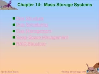
Industry has agreed on a standardizedscheme for multiple-disk database design, known as RAID (redundant array of independentdisks). The RAID scheme consists of seven levels,2 zero through six.These levels do notimply a hierarchical relationship but designate different designarchitectures that share three common characteristics: • 1. RAID is a set of physical disk drives viewed by the operatingsystem as a single logical drive. • 2.Data are distributed across the physical drives of an array in ascheme known as striping, described subsequently. • 3.Redundant disk capacity is used to store parity information,which guaranteesdata recoverability in case of a disk failure.
A disk cache is a buffer in main memory for disk sectors.The cache contains a copy of some of the sectorson the disk.When an I/O request is made for a particular sector, a check is made todetermine if the sector is in the disk cache. If so, the request is satisfied via the cache. Ifnot, the requested sector is read into the disk cache from the disk. Because of the phenomenonof locality of reference,when a block of data is fetched into the cache to satisfya single I/O request, it is likely that there will be future references to that same block.
Design Considerations • Several design issues are of interest. First, when an I/O request is satisfied from thedisk cache, the data in the disk cache must be delivered to the requesting process.Thiscan be done either by transferring the block of data within main memory from thedisk cache to memory assigned to the user process, or simply by using a shared memorycapability and passing a pointer to the appropriate slot in the disk cache. • The most commonly used algorithm is least recently used (LRU): Replace that block that hasbeen in the cache longest with no reference to it. Logically, the cache consists of astack of blocks, with the most recently referenced block on the top of the stack.When a block in the cache is referenced, it is moved from its existing position on thestack to the top of the stack.When a block is brought in from secondary memory,remove the block that is on the bottom of the stack and push the incoming blockonto the top of the stack. Naturally, it is not necessary actually to move these blocksaround in main memory; a stack of pointers can be associated with the cache.
Another possibility is least frequently used (LFU): Replace that block in theset that has experienced the fewest references. LFU could be implemented by associatinga counter with each block.When a block is brought in, it is assigned a countof 1; with each reference to the block, its count is incremented by 1.When replacementis required, the block with the smallest count is selected. Intuitively, it mightseem that LFU is more appropriate than LRU because LFU makes use of morepertinent information about each block in the selection process.
Performance Considerations • The issue of cache performance reduces itself to a question of whether a given miss ratiocan be achieved. This will depend on the locality behavior of the disk references,the replacement algorithm, and other design factors.
> Figure 11.11 shows results for simulation studies of the frequency-based replacement algorithm. A comparisonof the two figures points outone of the risks of this sort of performance assessment • > when identical reference patterns using the sameCachestructurearecompared, the frequency-based replacement algorithm is superior.