
Introduction
Mode. Frequency. Description. Nodal Position. 1. 1.712 MHz. Quarter wave Device. Transducer face. 2. 2.274 MHz. Quarter wave cavity. Pyrex boundary. 3. 3.442 MHz. Half wave device. Cavity, between centre and pyrex. 4. 4.100 MHz. Half wave cavity. mid cavity.

Introduction
E N D
Presentation Transcript
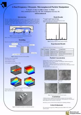
Mode Frequency Description Nodal Position 1 1.712 MHz Quarter wave Device Transducer face 2 2.274 MHz Quarter wave cavity Pyrex boundary 3 3.442 MHz Half wave device Cavity, between centre and pyrex 4 4.100 MHz Half wave cavity mid cavity A Dual Frequency, Ultrasonic, Microengineered Particle Manipulator N. Harris1*, Y. Shen2, M. Hill2, S. Beeby1 , N. White1 1ECS, Southampton University, UK; 2SES, Southampton University, UK; nrh@ecs.soton.ac.uk • Introduction • Ultrasonic standing waves can be used to generate forces on particles within a fluid. Recent work has concentrated on developing devices that manipulate the particles so that they are concentrated near the centre of the cavity. It is also possible to design a device that concentrates the particles at the wall of a cavity. This paper describes a device that has the capability of operating in several modes to allow concentration of particles at either the cavity wall or the centre on the cavity. • Figure 1: A Cross-section of an acoustic particle manipulator • Figure 1 shows a cross-section of a typical device • Modelling • The device is modelled as a multilayer structure as shown in figure 2. • Figure 2: Multilayer structure used for modelling • Modelling carried out using Matlab • Pyrex thickness of 1700um • Silicon thickness of 525um • Cavity depth varied from 160um to 195um • Optimum depth to see all four modes is 175um • Figure 4 shows the device mounted on a manifold • Figure 4: Manipulator mounted on an aluminium manifold • Model Results • The 4 modes of interest are are predicted at • 1.8MHz, 2.3MHz, 3.5MHz and 4.2MHz • Quarter wave modes are less efficient than half wave modes • Figure 5 shows the relative performance • Figure 5: Energy frequency product against frequency • Experimental Results • 4 modes were found at the frequencies shown in table 1 • Particle Concentration • A microscope was used to focus on the nodal planes • Particles of yeast were seen to concentrate in nodal planes at different frequencies • The frequencies were as in table 1 • Figure 6 shows a sequence describing the concentrating effect for mode 1 • Over a period of 20 seconds, particles can be seen to be in focus, indicating movementinto the focal plane • The other modes showed similar results Figure 5: Pressure profiles of the 4 main modes Figure 7: Showing particles moving to the pyrex boundary Conclusions A Multimodal micro machined acoustic particle concentrator has been modelled, constructed, and the model verified experimentally, allowing particles to be positionedeither within the cavity or driven to a cavity face. Such devices can be constructed using standard micro machining techniques. Acknowledgements This work has been supported by EPSRC grant number GR/R13333/01, DSTL,and Porvair PLC.


