Analysis and Modeling of Electrical Circuits with Resistors and Capacitors
This document discusses the modeling of electrical circuits involving resistors and capacitors, focusing on various configurations. Example 3.1 examines a circuit with input voltage V1, inductance L, capacitance C, and two different resistors R1 and R2. It presents characteristic equations and eigenvalues, aiding in understanding dynamic responses. Further, Example 3.2 delineates generalized charges in an operational amplifier setup with different resistor and capacitor values. Eigenvalues from both examples illustrate circuit behavior, revealing insights into system stability and performance.

Analysis and Modeling of Electrical Circuits with Resistors and Capacitors
E N D
Presentation Transcript
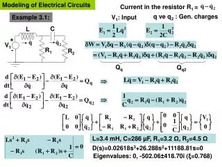
Modeling of Electrical Circuits C L + V1 - R1 R2 Qq Qq2 Current in the resistor R1 = q ve q2 : Gen. charges Example 3.1: V1: Input L=3.4 mH, C=286 µF, R1=3.2 Ω, R2=4.5 Ω D(s)=0.02618s3+26.288s2+11188.81s=0 Eigenvalues: 0, -502.06±418.70i (ξ=0.768)
In op-amp input, resistance is too high C1 R3 C2 R1 V1 V2 R2 - + Example3.2 Input :V1 Generalized charges: q1, q2, q3 Also, in op-amp: V+=V-=0
R1=15.9 kΩ, R2=837 Ω, R3=318 kΩ, C1=C2=0.005 µF Eigenvalues: 0, -628.93±12561.76i (ξ=0.05)
C R2 R R1 V2 V2 V1 V1 V1 R - - - C + + + V2
R R R R R R R R R V3 V2 V1 Vc - - V1 - + + + Vc + V1 - Vc V2 V2
C3 R2 R3 R1 R R R R4 - - - V1 R + + + C4 V2 - + PID control circuit