Download

1 / 40
400 likes | 526 Vues
This paper provides an overview of physics results from the National Spherical Torus Experiment (NSTX-U), focusing on research targets in predictive physics for fusion energy development. The study explores unique ST plasmas to enhance understanding for tokamaks, challenges theory, and advances toward non-inductive operation. Key physics aspects, high beta plasma transport, stability, and mitigation methods to control heat/particle flux are discussed. The paper also covers the impact of lithium evaporation on plasma characteristics and the effectiveness of lithium-graphite interfaces in deuterium pumping. Experimental measurements and simulations illustrate the importance of oxygen in the lithium-graphite system and its role in retaining deuterium. Kinetic stability and global stability experiments further support the findings and offer insights for future research.

E N D
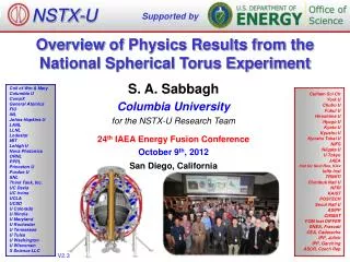
NSTX-U Supported by Overview of Physics Results from the National Spherical Torus Experiment S. A. Sabbagh Columbia University for the NSTX-U Research Team Coll of Wm & Mary Columbia U CompX General Atomics FIU INL Johns Hopkins U LANL LLNL Lodestar MIT Lehigh U Nova Photonics ORNL PPPL Princeton U Purdue U SNL Think Tank, Inc. UC Davis UC Irvine UCLA UCSD U Colorado U Illinois U Maryland U Rochester U Tennessee U Tulsa U Washington U Wisconsin X Science LLC Culham Sci Ctr York U Chubu U Fukui U Hiroshima U Hyogo U Kyoto U Kyushu U Kyushu Tokai U NIFS Niigata U U Tokyo JAEA Inst for Nucl Res, Kiev Ioffe Inst TRINITI Chonbuk Natl U NFRI KAIST POSTECH Seoul Natl U ASIPP CIEMAT FOM Inst DIFFER ENEA, Frascati CEA, Cadarache IPP, Jülich IPP, Garching ASCR, Czech Rep 24thIAEA Energy Fusion Conference October 9th, 2012 San Diego, California V2.1
NSTX research targets predictive physics understanding needed for fusion energy development facilities • Enable devices: ST-FNSF, ST-Pilot/DEMO, ITER • Leveraging unique ST plasmas provides new understanding for tokamaks, challenges theory Fusion Nuclear Science Facility (FNSF) ST Pilot Plant Outline ITER • Develop key physics understanding to be tested in unexplored, hotter ST plasmas • Study high beta plasma transport and stability at reduced collisionality, for extended pulse • Prototype methods to mitigate very high heat/particle flux • Move toward fully non-inductive operation NSTX-U New center-stack 2nd neutral beam 3D effects are pervasive in this research 12 MW 1 T 0.5 6 BT Ip PNBI pulse 1 1 2 MA 5 s
First successful nonlinear microtearing simulations for NSTX predict reduced electron heat transport at lower collisionality Theory Experiment • Predicted ce and scaling ~ ne1.1 consistent with experiment (WtE ~ BttE ~ n*e-0.8) • Transport dominated by magnetic “flutter” • Significant dBr/B ~ 0.1% dBr(Gauss) experiment BttE(T-s) cesim ~ ne1.1 120968 W. Guttenfelder, et al., PRL 106 (2011) 155004 n*e(at r/a = 0.5) • Increase in tE as n*e decreases • Trend continues when lithium is used Kaye EX/7-1 Guttenfelder TH/6-1 • NSTX-U computed to extend studies down to < 1/4 of present n*
Plasma characteristics change nearly continuously with increasing lithium evaporation; reach kink/peeling limit 1.0 Bootstrap current profile 0.8 0.6 XGC0 model 0.4 Norm. surface avg. current 0.2 Sauter model Energy Confinement Time (ms) 0.0 0.5 0.6 0.7 0.8 0.9 1.0 yN Pre-discharge lithium evaporation (mg) R. Maingi, et al., PRL 107(2011) 145004 • Global parameters generally improve • ELM frequency declines - to zero • ELMs stabilize • Edge transport declines • As lithium evaporation increases, transport barrier widens, pedestal-top χereduced • New bootstrap current calculation (XGC0 code) improves agreement with profile reaching kink/peeling limit Diallo EX/P4-04 Maingi EX/11-2 Canik EX/P7-16 Chang TH/P4-12
Simulations and lab results show importance of oxygen in lithium-graphite PMI for pumping deuterium • Quantum-classical atomistic simulations show surface oxygen plays key role in the retention of deuterium in graphite D • Accordingly, lab results support that Li on graphite can pump D effectively due to O • XPS measurements show 2 µm of Li increases surface oxygen content of lithiated graphite to ~10% • deuterium ion irradiation of lithiated graphite greatly enhances oxygen content to 20%-40% • In stark contrast, D irradiation of graphite without Li decreases amount of surface O • Li acts as an O getter, and the O retains D % P. Krstic, sub. to Nature Comm. O C Li 1 2 3 4 5 atomic composition D+ bombarded Li-graphite D+ bombarded graphite Jaworski EX/P5-31 J.P. Allain, Taylor (Purdue U.)
Experiments measuring global stability vs. n further support kinetic RWM stability theory, provide guidance for NSTX-U Exp: Resonant Field Amplification (RFA) vsn Theory: RWM growth rate vs. n and wf unstable off resonance Marginal stability Collisionality RWM growth rate (γτw) off-resonance on resonance on resonance Plasma Rotation MISK code (trajectories of 20 experimental plasmas) • Two competing effects at lower n • Collisional dissipation reduced • Stabilizing resonant kinetic effects enhanced (contrasts early theory) • Expectations at lower n • More stabilization near ωφ resonances; almost no effect off-resonance • Mode stability directly measured in experiment using MHD spectroscopy • Decreases with n at lower RFA (“on resonance”) • Independent of n at higher RFA (“off resonance”) Bplasma RFA = Bapplied Berkery EX/P8-07 J. Berkery et al., PRL 106 (2011) 075004
BES measured low-k turbulence in ELM-free H-mode pedestal steep gradient region is most consistent with TEMs Beam emission spectroscopy (BES) array Poloidal Correlation Length vs. Parameters Z R • Multivariate linear scaling coefficients ak • Turbulence measurements in the steep gradient of the pedestal • Most consistent with Trapped Electron Modes • Partially consistent with KBM and m-Tearing Modes • Least consistent with ITG Modes • Measurements during MHD quiet periods, in steep gradient region • Large poloidal correlation lengths • kq≈ 0.2-0.4 cm-1 and kqri ≈ 0.2 Smith EX/P7-18
Pedestal width scaling differs from tokamaks; turbulence correlation measurements consistent with theory Turbulence correlation lengths Pedestal width scaling 0.16 (During inter-ELM period, at pedestal top) Theory (non-linear XGC1 code) 1.05 0.4 (bqped) NSTX Experiment 0.12 Pedestal width (yN) 0.08 C-Mod radial DIII-D 0.04 poloidal 0.5 ~ 0.08 (bqped) 0.00 80% - 99% ELM cycle R = 1.38m 139047 0.1 0.3 0.5 0.7 0.9 • Pedestal width scaling bqa applies to multiple machines • In NSTX, observed ped. width is larger • Data indicates stronger scaling: bq vs. bq0.5 • Examining possible aspect ratio effects • Measured correlation lengths at pedestal top are consistent with theory • BES and reflectometry • spatial structure exhibits ion-scale microturbulence (k⊥ri ~ 0.2 - 0.7) • Compatible with ITG modes and/or KBM Diallo EX/P4-04 A. Diallo, C.S. Chang, S. Ku (PPPL), D. Smith (UW), S. Kubota (UCLA) 8 8
Unstable RWM Stable / controlled RWM Stability control improvements significantly reduce unstable RWMs at low li and high bN; improved stability at high bN/li Resonant Field Amplification (RFA) vs. bN/li • Disruption probability reduced by a factor of 3 on controlled experiments • Reached 2 times computed n = 1 no-wall limit of bN/li = 6.7 • Lower probability of unstable RWMs at high bN/li unstable mode • Mode stability directly measured in experiments using MHD spectroscopy • Stability decreases up to bN/li= 10 • Stability increasesat higher bN/li • Presently analysis indicates consistency with kinetic resonance stabilization S.A. Sabbagh Berkery EX/P8-07
Disruptivitystudies and warning analysis of NSTX database are being conducted for disruption avoidance in NSTX-U Disruptivity Warning Algorithms • Disruption warning algorithm shows high probability of success • Based on combinations of single threshold based tests bN q* li All discharges since 2006 • Physics results • Low disruptivity at relatively high bN~ 6; bN/bNno-wall(n=1)~ 1.3-1.5 • Consistent with specific disruption control experiments, RFA analysis • Strong disruptivity increase for q* < 2.5 • Strong disruptivity increase for very low rotation • Results • ~ 98% disruptions flagged with at least 10ms warning, ~ 6% false positives • False positive count dominated by near-disruptive events Gerhardt EX/9-3
Improved stability control includes dual field component feedback and state space feedback, improved by 3D effects Active n = 1 Bp+ BRfeedback (FB) control Calculation of Br+ Bpcontrol (VALEN) 1 2.8 6 Feedback on 140124 140125 140126 140127 bN 0 deg FB phase 4 2.7 2 Br FB phase = 225o 2.6 0 2 Radial field n = 1 (G) Brn = 1 (G) 90 deg FB phase 6 Br FB phase = 180o 2.5 4 Vacuum error field + RFA 2.4 2 180 deg FB phase Vacuum error field 0 2.3 0.0 0.2 0.4 0.6 0.8 1.0 1.2 1.4 t (s) 0.0 0.04 0.08 0.12 Br FB phase = 0o Br FB phase = 90o Dt(s) (model) RWM State Space Controller No NBI port With 3D NBI port 3D wall, ports, mode currents Measurement Measurement Sensor Differences (G) Controller Controller • Inclusion of 3D mode and wall detail improves control S.A. Sabbagh, O. Katsuro-Hopkins, J.M. Bialek, S.P. Gerhardt
Fast ion redistribution associated with low frequency MHD measured by fast ion Da(FIDA) diagnostic Fast ion density reduction • Caused by n = 1 global kink instabilities • Redistribution can affect stability of *AE, RWMs, other MHD • Full-orbit code (SPIRAL) shows redistribution in real and velocity space • Radial redistribution from core plasma • Particles shift towards V||/V = 1 • Applied 3D fields alter GAE stability • By altered fast ion distribution (SPIRAL) 0.9 1.0 1.1 1.2 1.3 1.4 1.5 R(m) Change in distribution due to kink mode SPIRAL code V||\V • Fast ion energy redistribution accounts for neutron rate decrease in H-mode TAE avalanches • Core localized CAE/GAEs measured in H-mode plasmas (reflectometer) Z [m] CAE resonances Fredrickson EX/P6-05 R [m] Energy [keV] Crocker EX/P6-02 A. Bortolon
Significant fraction of the HHFW power lost in the SOL in front of antenna, flows to the divertor region Visible camera image of edge RF power flow to divertor SPIRAL modeling of field lines from antenna to divertor • RF power couples to field lines across entire SOL width, not just to field lines connected to antenna components • Shows importance of quantitatively understanding RF power coupling to the SOL for prediction to future devices Top View Divertor HHFW Antenna Divertor HHFW Antenna -1.0 0.0 1.0 R(m) Perkins EX/P5-40 R. Perkins, et al., PRL 109 (2012) 045001
Snowflake divertor experiments provide basis for required divertor heat flux mitigation in NSTX-U Snowflake divertor in NSTX • Needed, as divertorheat flux width strongly decreases as Ipincreases • Snowflake divertor experiments (PNBI = 4 MW, PSOL = 3 MW) • Good H-mode tE, bN, sustained during snowflake operation • Divertor heat flux significantly reduced both during and between ELMs • during ELMs: 19 to ~ 1.5 MW/m2 • steady-state: 5-7 to ~ 1 MW/m2 • Achieved by a synergistic combination of detachment + radiative snowflake divertor Z (m) R (m) Heat flux at peak ELM time Divertor heat flux (MW/m2) CHI gap R (m) Soukhanovskii EX/P5-21
Toroidal asymmetry of heat deposition measured during standard ELMs, but decreases for 3D field-triggered ELMs Toroidal Degree of Asymmetry vs. qpeak Mean Peak 2D Heat Flux During ELMs vs. t • 2D fast IR camera measurement (6.3kHz), heat flux from TACO code • Toroidal asymmetry • Becomes largest at the peak heat flux for usual Type-I ELMs • Reduced by up to 50% in ELMs triggered by n = 3 applied fields No 3D fields Reduction with 3D fields Standard ELMs 132438 Type-I ELMs qpeak,2D (MW/m2) DoA(qpeak) n=3 triggered at ELM peak times ,2D Ahn EX/P5-33
L-mode discharge ramping to 1MA requires 35% less inductive flux when coaxial helicity injection (CHI) is used CHI assisted startup in NSTX TSC simulation of CHI startup 1.0 ms 1.6 ms 2.7ms 2 1 Z (m) 0 -1 -2 High elongation 0 1 2 0 0 1 2 1 2 R (m) R (m) R (m) • CHI generates plasmas with high elongation, low li and ne • TSC now used for full discharge modeling to 1MA • CHI start-up + NBI current ramp-up • Results imply a doubling of closed flux current > 400kA in NSTX-U Low inductance Raman EX/P2-10 Low density
Non-inductive current fractions of up to 65% sustained in NSTX, >70% transiently; Upgrade projected to achieve 100% NSTX-U projections • Maximum sustained non-inductive fractions of 65% w/NBI at IP = 0.7 MA NSTX Results NSTX Results Total Non-inductive Fraction BT=1 T BT=0.75 T BT=0.75 T NSTX-U (100% NI) via high harmonic FW BT=1 T (ranges created by profile peakedness, tEscalings, etc.) Ip (MA) • 100% non-inductive scenarios found over wide operation range • Scenarios at 74% Greenwald density • 70- 100% non-inductive reached transiently using HHFW CD G. Taylor (Phys. Plasmas 19 (2012) 042501) Menard FTP/3-4 S. Gerhardt, et al., Nucl. Fusion 52(2012) 083020
Rapid Progress is Being Made on NSTX Upgrade NEW Center Stack Old center stack • 2nd neutral beam moved into place TF OD = 20cm TF OD = 40cm • TF conductors being made (first plasma anticipated June 2014) Menard FTP/3-4
Continuing analysis of NSTX data targets a predictive physics understanding required for future fusion devices • Transport and stability at reduced collisionality • tEscalingsunified by collisionality; non-linear microtearing simulations match experimental ce, predict lower ceat lower ne* shown in experiment • Nearly continuous increase of favorable confinement with increased lithium • Stabilizing kinetic RWM effects enhanced at lower n when near resonances • Pedestal • Width scaling stronger than usual (bpped)0.5; measured dnecorrelation lengths consistent w/non-linear gyrokineticsat pedestal top • Pulse sustainment / disruption avoidance • Global stability increased+ low disruptivityat high bN/li, advanced mode control • Disruption detection algorithm shows high (98%) success rate • Power/particle handling and first wall • Large heat flux reduction from synergistic combination of radiative snowflake divertor + detachment, both during, and between ELMs • Significant upgrade underway (NSTX-U) • Doubled BT, Ip, NBI power;5x pulse length, projected 100% non-inductive sustainment over broad operating range
NSTX Presentations at the 2012 IAEA FEC Talks Posters
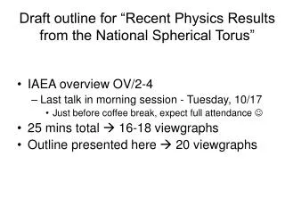
Tasks to Complete for this Presentation • Additions • Add bullet on L-H power threshold – REF Battaglia talk EX/P5-28 • Tasks • Shorten talk to 18 slides • Poster up to 24 slides
Plasma characteristics change nearly continuously with increasing lithium evaporation inside vessel Measured density fluctuation vs. k^rs • Measured reduction in high-k turbulence consistent with reduced ce • Impact of collisionalityand Ñn on turbulence is under investigation • BttE ~ ne*-0.8 observed Outer plasma R = 1.4 - 1.46 m (r/a = 0.74 – 0.95) Without Li Energy Confinement Time (ms) (dn/n)2 (arb) With Li Pre-discharge lithium evaporation (mg) 141314 141328 • Global parameters generally improve • ELM frequency declines - to zero • ELMs stabilize • Edge transport declines • As lithium evaporation increases, transport barrier widens, pedestal-top χereduced k^rs Maingi EX/11-2 Canik EX/11-2 Ren EX/P7-02
Kinetic RWM stability theory further tested against NSTX experiments, provides guidance for NSTX-U MISK code RWM stability vs. wf RWM growth rate contours (gtw) Marginal Stability unstable NSTX NSTX-U Collisionality Plasma Rotation • Two competing effects at lower n • Collisional dissipation reduced • Stabilizing resonant kinetic effects enhanced (contrasts early theory) • Expectations at lower n • More stabilization near ωφ resonances; almost no effect off-resonance • Active RWM control important • Improvements to physics model • Anisotropy effects • Testing terms thought small • Already good agreement between theory and experiment of marginal stability point improved Berkery EX/P8-07 J. Berkery et al., PRL 106, 075004 (2011)
Experiments using MHD spectroscopy show that highest bN/liplasmas are not the least stable unstable RWMs 1.5 NSTX • Low frequency (40Hz) rotating n = 1 applied field used as seed field • n = 1 resonant field amplification (RFA) of seed field used to measure global mode growth rate in stable plasmas • Higher amplitude = less stability 1.0 n = 1 RFA (G/G) 0.5 0.0 15 10 5 bN/li Bplasma J.W. Berkery, S.A. Sabbagh RFA = Bapplied • Discharges with bN/li > 10 have greaterstability • Presently thought to be due to differing plasma rotation profile Berkery EX/P8-07
Higher aspect ratio of NSTX-U tested in NSTX, vertical stability growth rate data obtained, compared to simulation Vertical Stability Growth Rates vs. A • Improvements to vertical control capability and understanding • Begun to compare measured growth rates to theoretical predictions (Corsica, GSPERT) • Improved plasma position observer • Modeled use of RWM coils for n=0 control 5 4 3 2 1 GSPERT Corsica Experiment g/g0 NSTX-U PFC Boundary 1.5 1.55 1.6 1.65 Aspect Ratio • NSTX Discharges have matched aspect ratio and elongation of NSTX-U without performance degradation Kolemen EX/P4-28
Single summary slides follows • NOTE: The single summary slide is not an adequate summary
OV/3-1: NSTX research targets needed predictive physics understanding crucial for fusion energy development • Enable devices: ST-FNSF, ST-Pilot/DEMO, ITER • Leveraging unique ST plasmas provides new understanding for tokamaks, challenges theory Highlights Fusion Nuclear Science Facility (FNSF) ITER • Transport, stability at reduced collisionality • tEscalingsunified by collisionality; microtearing code matches XP ce, predicts lower ceat lower ne* • Stabilizing kinetic RWM effects enhanced • Pedestal • Width scaling stronger than usual (bpped)0.5; measured dnecorrel. lengths agree w/non-linear gyrokinetics • Pulse sustainment / disruption avoidance • Global stability increased + low disruptivityat high bN • Power/particle handling and first wall • Radiative snowflake divertormitigates high heat flux both between & during ELMs, Li wall cond. effects • Significant upgrade underway (NSTX-U) • Doubled BT, Ip, NBI power, non-inductive sustainment kink-induced fast ion redistribution te vs. collisionality non-inductive scenarios disruption warning analysis
Breakdown of Topics in Talk Should have 18 slides total (17 plus 1 reference to other talks) • Advanced Scenarios and Control 2 slides • Boundary Physics / Pedestal 1 slides • Lithium Research 2 slides • Macroscopic Stability 4 slides • Solenoid-free Start-up / Ramp-up 1 slides • Transport and Turbulence 3slides • Waves and Energetic Particles 1 slides • Title, intro, summary, reference 4 slides Total 18 slides
NSTX Overview presentation and papers – preparation IAEA FEC 2012 (discussion on 8/13/12) • Presentation length • Past talks: average of 13.5 slides in 17 minutes (0.8/min), suggests: • Overview: 17 slides in 21 minutes (+ 4 minutes for questions) • Presentation status / needs (thanks for material sent so far!) • Working from NSTX PAC talk (approximately same length) • Will update with most recent analysis from NSTX Team • Papers • 12 page proceedings paper • Longer Nuclear Fusion paper • Paper Preparation • Most contributors sent slides, not text – please send text/references ! • Some text available from EPS 2012 presentations, but not all topics are covered • Will send further requests for input / seek out new results V1.0
NSTX research targets predictive physics understanding needed for fusion energy development facilities • Enable key ST applications • Move toward steady-state ST FNSF, pilot plant • Close key gaps to DEMO • Extend understanding to tokamak / ITER • Leverage ST to test theory, develop predictive capability Fusion Nuclear Science Facility (FNSF) ST Pilot Plant Outline ITER • Develop key physics understanding to be tested in unexplored, hotter ST plasmas • Study high beta plasma transport and stability at reduced collisionality, extended pulse • Prototype methods to mitigate very high heat/particle flux • Move toward fully non-inductive operation NSTX-U New center-stack 2nd Neutral Beam 1 T 12 MW BT Ip PNBI pulse 3D effects are pervasive in this research 2 MA 5 s
Pedestal scaling, structure, and dynamics studied theoretically and experimentally Turbulence correlation lengths Pedestal width scaling (During inter-ELM period, at pedestal top) Theory (non-linear XGC1 code) Experiment radial MAST C-Mod DIII-D JET poloidal 80% - 99% ELM cycle R = 1.38m 139047 • Pedestal width scaling bqa applies to multiple machines • In NSTX, observed ped. width is larger • 1.7 x MAST, 2.4 x DIII-D • Data indicates stronger for NSTX: bq0.94 vs. bq0.5 • Measured correlation lengths at pedestal top are consistent with theory • BES and reflectometry • spatial structure exhibits ion-scale microturbulence (k⊥ri ~ 0.2 - 0.7) • Compatible with ITG and/or KBM Diallo EX/P4-04 A. Diallo, C.S. Chang, S. Ku (PPPL), D. Smith (UW), S. Kubota (UCLA) 34 34
Experiments measuring global stability vs. n further support kinetic RWM stability theory, provide guidance for NSTX-U Exp: Resonant Field Amplification (RFA) vsn Theory: RWM growth rate contours (gtw) “off resonance” Marginal Stability unstable NSTX NSTX-U “on resonance” Collisionality Plasma Rotation MISK code (trajectories of 20 experimental plasmas) • Two competing effects at lower n • Collisional dissipation reduced • Stabilizing resonant kinetic effects enhanced (contrasts early theory) • Expectations at lower n • More stabilization near ωφ resonances; almost no effect off-resonance • Mode stability directly measured in experiment using MHD spectroscopy • Decreases with n at lower RFA (“on resonance”) • Independent of n at higher RFA (“off resonance”) Bplasma RFA = Bapplied J. Berkery et al., PRL 106, 075004 (2011) Berkery EX/P8-07
0.56 0.58 0.58 0.60 0.60 0.62 0.62 Improved stability control includes dual field component feedback and state space feedback with 3D structure Active n = 1 Bp+ BRfeedback (FB) control Calculation of Br+ Bpcontrol (VALEN) 2.8 6 Feedback on 140124 140125 140126 140127 bN 0 deg FB phase 4 2.7 2 Br FB phase = 225o 2.6 0 Radial field n = 1 (G) Brn = 1 (G) 90 deg FB phase 6 Br FB phase = 180o 2.5 4 Vacuum error field + RFA 2.4 2 180 deg FB phase Vacuum error field 0 2.3 0.0 0.2 0.4 0.6 0.8 1.0 1.2 1.4 t (s) 0.0 0.04 0.08 0.12 Br FB phase = 0o Br FB phase = 90o Dt(s) (model) RWM State Space Controller 2 states 7 states Measurement Measurement 200 3D wall, ports, mode currents dBp180 dBp180 100 Sensor Differences (G) 0 -100 Controller (observer) Controller (observer) t (s) t (s) • Significantly reduced disruptions at high bN in controlled experiments S.A. Sabbagh, O. Katsuro-Hopkins, J.M. Bialek
Fast ion redistribution associated with low frequency MHD measured by fast ion Da(FIDA) diagnostic Fast ion density reduction • Caused by n = 1 global instabilities • Primarily n = 1, weaker n = 2 present • Redistribution can affect stability of *AE, RWMs, other MHD • CAE activity observed after onset of low frequency MHD • Full-orbit code (SPIRAL) shows redistribution in real and velocity space • Radial redistribution from core plasma • Particles shift towards V||/V = 1 0.9 1.0 1.1 1.2 1.3 1.4 1.5 R(m) Change in distribution due to kink mode SPIRAL code V||\V Z [m] CAE resonances • Measured CAE and GAEs (reflectometer) in H-mode core plasmas • mode #, frequency measured: modes peak in core, resonant with electron orbit frequencies R [m] Energy [keV] Crocker EX/P6-02 A. Bortolon
Snowflake divertor experiments provide basis for required divertor heat flux mitigation in NSTX-U Snowflake divertor in NSTX • Needed for NSTX-U, as divertorheat flux width strongly decreases as Ipincreases • Snowflake divertor experiments (PNBI = 4 MW, PSOL = 3 MW) • Good H-mode tE, bN, sustained during snowflake operation • Divertor heat flux significantly reduced both during and between ELMs • during ELMs: 19 to < 1 MW/m2 • steady-state: 7 to < 1 MW/m2 • Achieved by a synergistic combination of detachment + radiative snowflake divertor OSP Divertor heat flux (MW/m2) Soukhanovskii EX/P5-21
Significant fraction of the HHFW power may be lost in the SOL in front of antenna and flow to the divertor region View from Top Divertor HHFW Antenna Divertor HHFW Antenna SPIRAL results show field lines (green) spiraling from SOL in front of HHFW antenna to divertor Visible camera image shows edge RF power flow follows magnetic field from antenna to divertor • Field line mapping predicts RF power deposited in SOL, not at antenna face • 3D AORSA will assess surface wave excitation in NSTX-U • Proposed DIII-D experiment to look for RF edge losses during 2012 run • NSTX-U experiments and modeling to emphasize HHFW heating of high NBI power, long-pulse H-modes assess effect of varying outer gap R. J. Perkins, et al., PRL (2012) Perkins EX/P5-40
Rapid Progress is Being Made on NSTX Upgrade NEW Center Stack Old center stack • 2nd NBI box moved into place TF OD = 20cm TF OD = 40cm • TF conductors being made (first plasma anticipated June 2014) Menard FTP/3-4